Air intake mechanism of electronic apparatus, and image forming apparatus provided with air intake mechanism

a technology of air intake mechanism and electronic apparatus, which is applied in the direction of electrical apparatus construction details, instruments, and electrical apparatus casings/cabinets/drawers, etc., can solve the problems of adversely affecting peripheral electronic apparatuses, leakage of electromagnetic noise occurring from electronic components on control boards, and noise (wind sound) occurring, so as to curb the occurrence of wind sound, the effect of reducing the noise produced by the vibration of the inner cover

Inactive Publication Date: 2015-01-01
KYOCERA DOCUMENT SOLUTIONS INC
View PDF5 Cites 7 Cited by
  • Summary
  • Abstract
  • Description
  • Claims
  • Application Information

AI Technical Summary

Benefits of technology

[0015]According to the first structure of the present disclosure, a plurality of airflows, which flow in through the second louver that is formed of the plurality of linear slits, join each other and flow to the first louver that is formed of the annular opening. And, the airflows pass through the first louver, thereafter, are pulled into the axial-flow fan; accordingly, the airflows flowing in through the second louver do not branch when passing through the first louver, so that it is possible to curb occurrence of a wind sound. Besides, by making the opening width of the annular opening that forms the first louver wider than the opening width of the linear slit that forms the second louver, it is also possible to curb occurrence of noise produced by vibration of the inner cover. Accordingly, it is possible to achieve quietness of the electronic apparatus and improve cooling effect in the electronic apparatus. Further, by forming the support portion, which supports the inner circular portion of the first louver, on the tangential line of the inner circular portion that extends from the circumferential rim portion of the outer circular portion toward the inner circular portion in the same direction as the circling direction of the airflow that is produced by the axial-flow fan, it is possible to reduce further interference between the support portion and the airflow that is produced by the axial-flow fan.
[0016]Besides, according to the second structure of the present disclosure, by incorporating the air intake mechanism having the above first structure, it is possible to achieve quietness of the image forming apparatus and smoothly pull cold air outside the image forming apparatus into the electric box; accordingly, cooling effect for the control board also improves.

Problems solved by technology

In such control boards, there is a risk that electromagnetic noise occurring from the electronic components on the control boards leak further to outside to adversely affect peripheral electronic apparatuses.
However, in the case where a fan is used to cool the control board, noise (wind sound) occurs when an airflow due to the fan passes through the air opening.
In recent years, the demand for reducing noise is increasing, and measures against a wind sound that is a factor of noise are becoming important, but the method of the patent document 1 cannot reduce the wind sound.

Method used


Image

  • Air intake mechanism of electronic apparatus, and image forming apparatus provided with air intake mechanism
  • Air intake mechanism of electronic apparatus, and image forming apparatus provided with air intake mechanism
  • Air intake mechanism of electronic apparatus, and image forming apparatus provided with air intake mechanism

Examples


Embodiment Construction

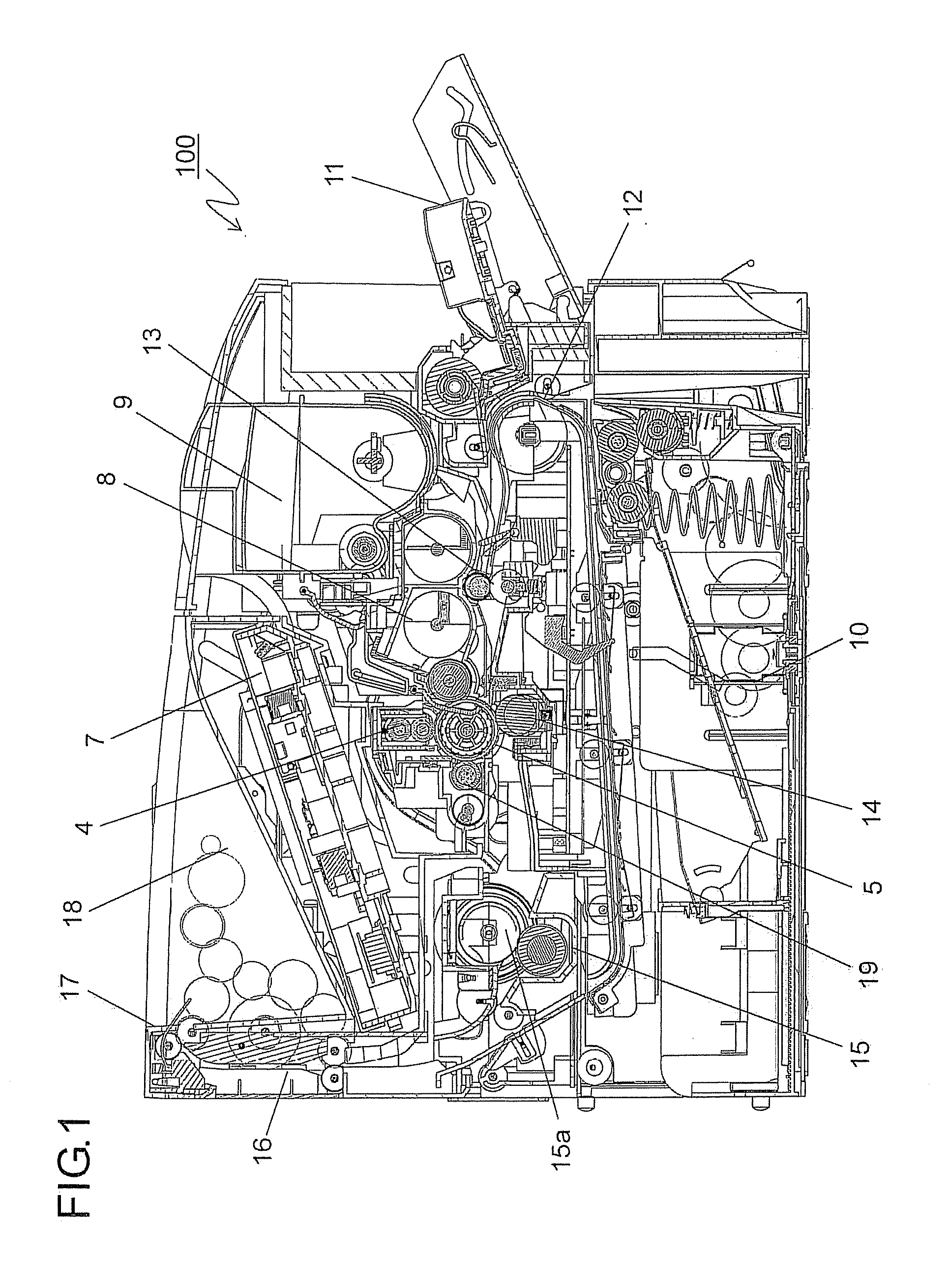
[0023]Hereinafter, an embodiment of the present disclosure is described with reference to the drawings. FIG. 1 is a side sectional view showing an internal structure of the image forming apparatus 100 that comprises an air intake mechanism according to the present disclosure. In the image forming apparatus (e.g., monochromic printer) 100, in a case of performing an image forming operation, a photosensitive drum 5, which rotates clockwise in the drawing, is evenly electrified by an electrification unit 4. And, an electrostatic latent image is formed on the photosensitive drum 5 by means of a laser beam from a light exposure unit (laser scan unit and the like) 7 based on document image data, and a developer (hereinafter, called a toner) is attached to the electrostatic latent image by a development unit 8 to form a toner image.

[0024]A toner supply to this development unit 8 is performed from a toner container 9. In the meantime, the image data are transmitted from a personal computer ...


PUM


Abstract

This air intake mechanism is configured of a first louver (23), a second louver (30), and an axial fan (33). The first louver (23) is an annular opening between an outer circular section (25), which is concentric to the rotating axis (rotation center) of the axial fan (33), and an inner circular section (27), which is concentric to the outer circular section (25). The second louver (30) is configured of a plurality of linear slits (30a), which are parallel to each other. The opening width (d2) of each of the slits (30a) that constitutes the second louver (30) is smaller than the opening width (d1) of the first louver (23).

Description

TECHNICAL FIELD[0001]The present disclosure relates to an air intake mechanism that introduces external air into OA machines such as a digital copy machine, a laser printer and the like and into electronic apparatuses such as a home appliance and the like.BACKGROUND ART[0002]In electronic apparatuses such as a copy machine, a personal computer, a television and the like, various control boards, on which a plurality of electronic components are mounted, are used. In such control boards, there is a risk that electromagnetic noise occurring from the electronic components on the control boards leak further to outside to adversely affect peripheral electronic apparatuses. As a measure to prevent the leakage of the electromagnetic noise, a method is employed, in which the control board is housed in a metal electric box that blocks the electromagnetic noise.[0003]On the other hand, generally, the control board generates heat because of operation of an electronic apparatus; accordingly, it ...

Claims


Application Information

Patent Timeline
Patent Type & Authority Applications(United States)
IPC IPC(8): G06F1/20G03G21/20
CPCH05K7/20181H05K7/20145G03G21/206
Inventor TANIDA, KEIICHI
Owner KYOCERA DOCUMENT SOLUTIONS INC
Why Eureka
Try Eureka