Fuel cell system and control method for fuel cell system
- Summary
- Abstract
- Description
- Claims
- Application Information
AI Technical Summary
Benefits of technology
Problems solved by technology
Method used
Image

Examples
first embodiment
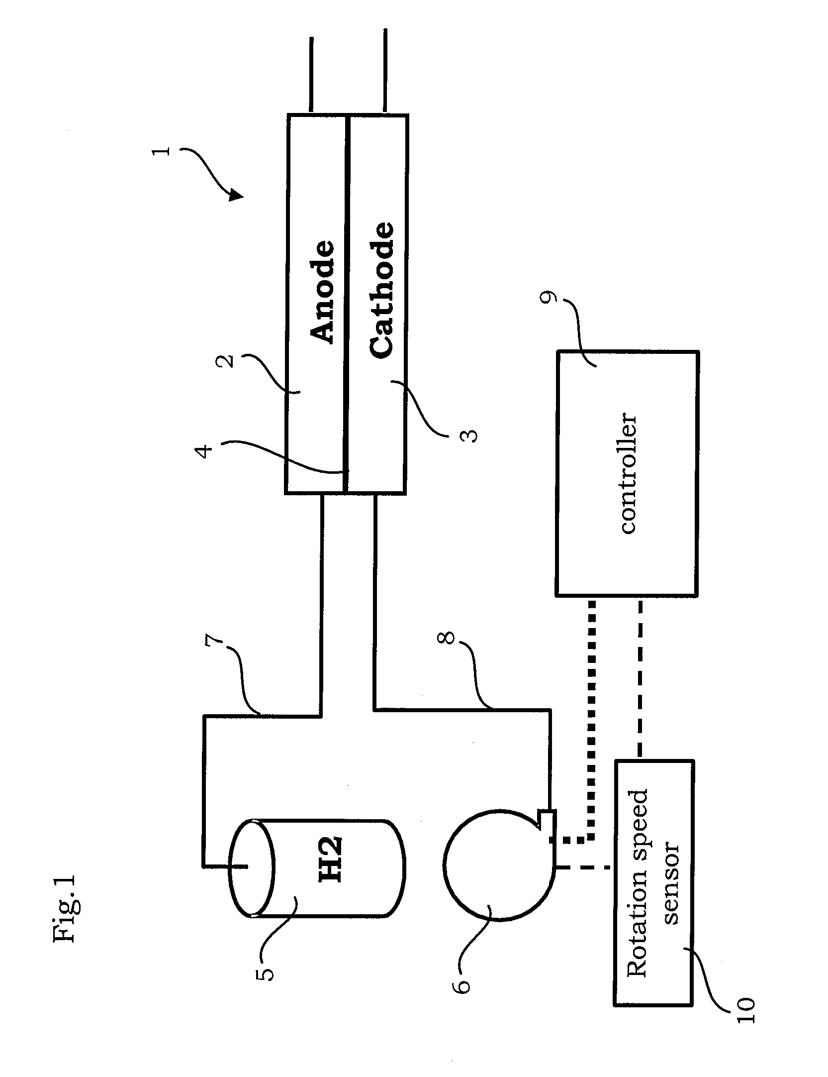
[0030]FIG. 1 is a view showing a system configuration according to a first embodiment of the present invention.
[0031]A fuel cell stack 1 is a direct current power supply constituted by a plurality of laminated single cells, each single cell being configured such that an electrolyte membrane 4 is sandwiched between an anode 2 and a cathode 3. It should be noted that FIG. 1 shows only one single cell.
[0032]Hydrogen gas is supplied to the anode 2 as a fuel from a hydrogen supply passage 7. Air is supplied to the cathode 3 as an oxidant gas from an air supply passage 8.
[0033]A pressure regulating valve, not shown in the figure, is interposed in the hydrogen supply passage 7. As a result, high pressure hydrogen in a hydrogen tank 5 is depressurized to a predetermined pressure and then supplied to the anode 2.
[0034]Air is supplied to the cathode 3 from the air supply passage 8 by a compressor 6. An air pressure in the cathode 3 is controlled by an air pressure regulating valve, not shown ...
second embodiment
[0078]FIG. 8 is a view showing a system configuration according to a second embodiment of the present invention.
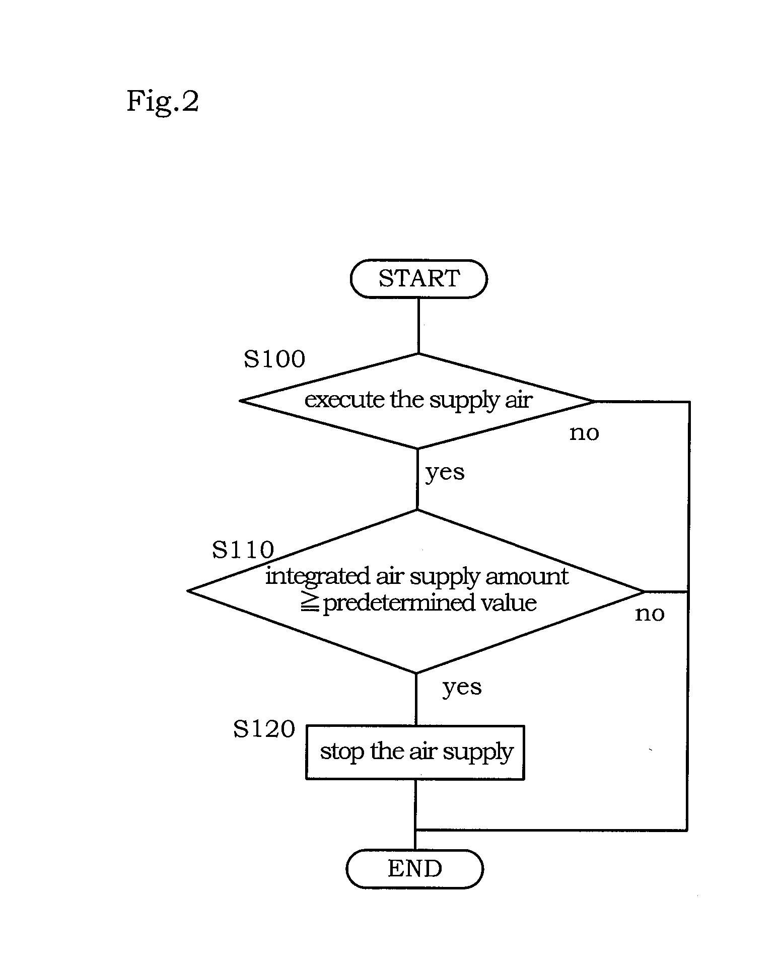
[0079]Likewise in this embodiment, when the average voltage of the fuel cell stack 1 falls to a preset voltage V0 during an idle stop, the controller 9 supplies air to the cathode 3 in order to restore the voltage. It should be noted that an overall voltage may be calculated, and air may be supplied when the overall voltage falls to a predetermined voltage.
[0080]Incidentally, when the amount of air supplied to the fuel cell stack 1 is insufficient, voltage decrease speed variation among the single cells increases, leading to a decrease speed difference between the minimum voltage and the average cell voltage of the stack. In other words, an amount of oxygen remaining in the stack correlates closely with the cell voltage. Hence, the controller 9 performs air supply control during an idle stop on the basis of the cell voltage.
[0081]FIG. 9 is a control block diagram showing a...
third embodiment
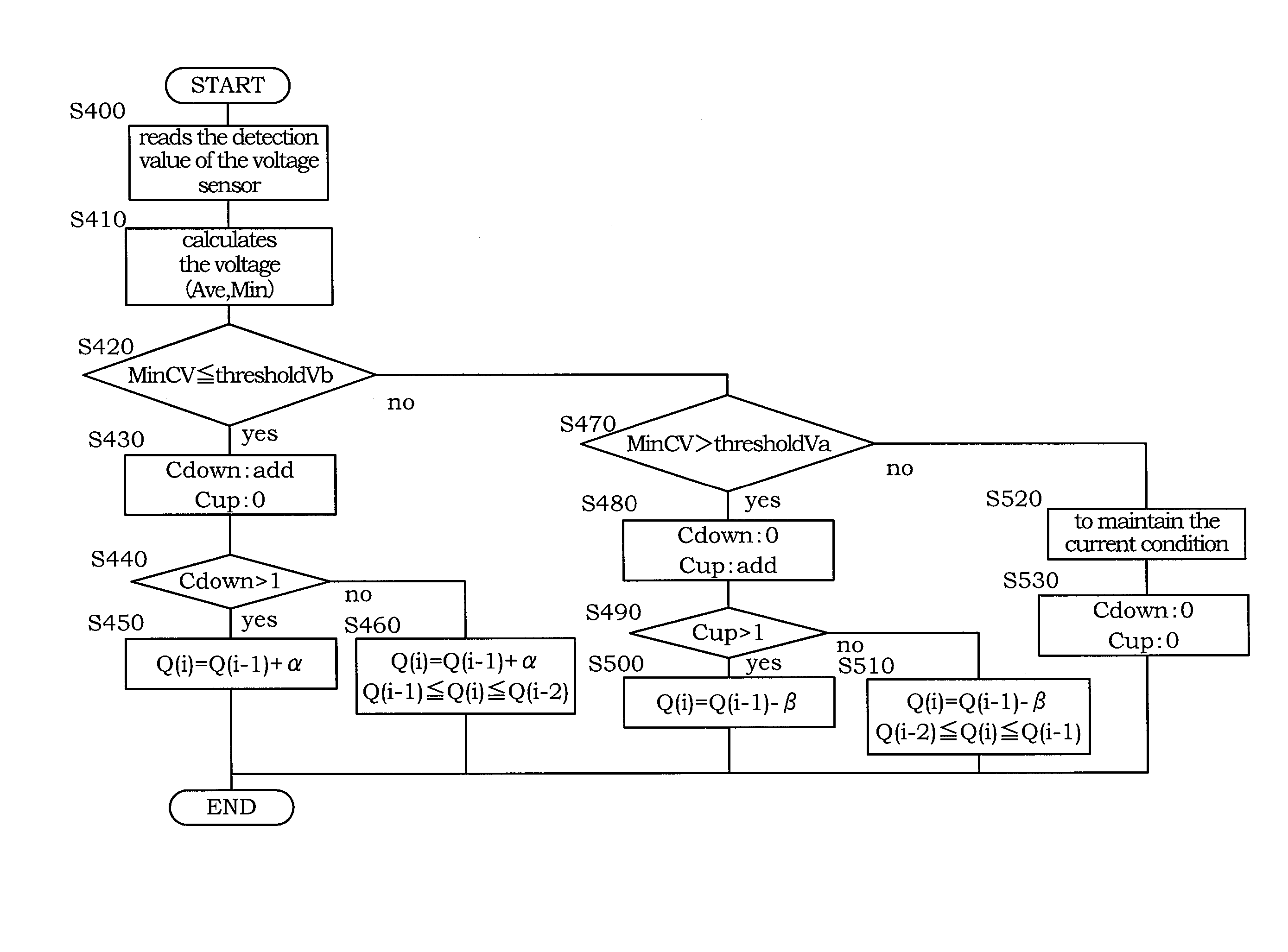
[0112]This embodiment is identical to the second embodiment in terms of the system configuration and the basic control routine, and differs only in the method of determining whether or not the amount of air supplied during an idle stop is appropriate. Hence, this difference will be described.
[0113]FIG. 16 is a flowchart showing a control routine for determining the air supply amount, which is executed by the controller 9 according to this embodiment.
[0114]In a step S300, the controller 9 reads the detection value of the voltage sensor 11.
[0115]In a step S310, the controller 9 calculates a voltage decrease speed ΔCV of the minimum voltage MinCV. It should be noted that the voltage decrease speed ΔCV is set at an absolute value of the speed. In other words, the voltage decreases steadily more quickly as a value of the voltage decrease speed ΔCV increases.
[0116]In a step S320, the controller 9 determines whether or not the voltage decrease speed ΔCV equals or exceeds the threshold Vb. ...
PUM
 Abstract
Description
Claims
Application Information
 - Generate Ideas
- Intellectual Property
- Life Sciences
- Materials
- Tech Scout
- Unparalleled Data Quality
- Higher Quality Content
- 60% Fewer Hallucinations
Browse by: Latest US Patents, China's latest patents, Technical Efficacy Thesaurus, Application Domain, Technology Topic, Popular Technical Reports.
© 2025 PatSnap. All rights reserved.Legal|Privacy policy|Modern Slavery Act Transparency Statement|Sitemap|About US| Contact US: help@patsnap.com