Method for calibrating a position-measuring system and position-measuring system

a technology of positionmeasuring system and positionmeasuring system, which is applied in the direction of measurement devices, instruments, photomechanical treatment, etc., can solve the problems of high cost of storing in the control unit, the method of calculating the shape change of the components involved in the measuring circuit, and the scaling error, so as to achieve the effect of improving the measuring accuracy

Active Publication Date: 2015-01-15
CARL ZEISS SMT GMBH
View PDF13 Cites 0 Cited by
  • Summary
  • Abstract
  • Description
  • Claims
  • Application Information

AI Technical Summary

Benefits of technology

[0007]In general, an aspect of the invention is to provide a method for calibrating a position-me

Problems solved by technology

Thus, e.g., large fluctuations in pressure can lead to errors in scaling because of compression of materials of components involved in measurement, such as e.g. the sample, the measuring section, the sample stage measurement mirror, etc.
Methods of calculating pressure-induced chan

Method used


Image

  • Method for calibrating a position-measuring system and position-measuring system
  • Method for calibrating a position-measuring system and position-measuring system
  • Method for calibrating a position-measuring system and position-measuring system

Examples


Embodiment Construction

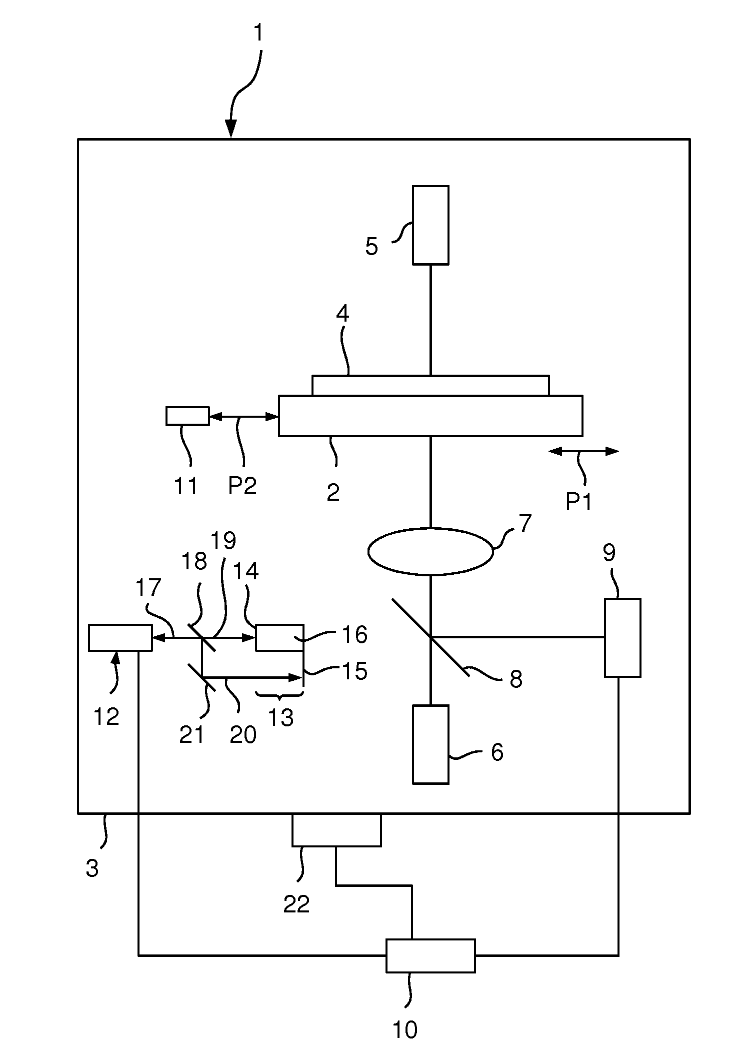
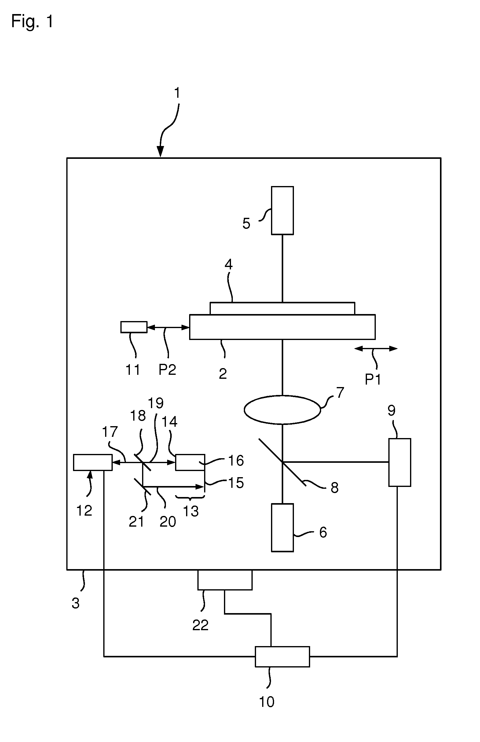
[0035]Referring to FIG. 1, in some implementations, a position-measuring system 1 includes a stage 2 which can be moved at least in one direction, which stage is arranged in a measuring area 3 in which a gaseous medium is present. The stage 2 bears a mask 4 to be examined, which mask is illuminated either by a first illumination device 5 for transillumination or a second illumination device 6 for incident illumination. The illumination device 5, 6 can for example each be developed as a laser which emits light with a wavelength of 193 nm.

[0036]The illuminated mask 4 is imaged via imaging optics 7 and a beam splitter 8 on an image sensor 9 (which for example is developed as a CCD sensor or as a CMOS sensor), which together can also be called recording unit or optical system. The image sensor 9 is connected to a control unit 10 arranged outside the measuring area 3 and said image sensor transmits the image signals to said control unit as first measuring signals.

[0037]In order to detect...


PUM


Abstract

A method is provided for calibrating a position-measuring system which includes the following steps: a) multiple measurements of a structure of a sample held by a sample stage at different pressures of the gaseous medium, in which the sample stage is arranged, b) ascertaining the pressure dependence when determining the position by use of an evaluation unit, c) establishing a calibration rule based on the ascertained pressure dependence, and d) applying the calibration rule when determining the position.

Description

CROSS-REFERENCE TO RELATED APPLICATIONS[0001]This application claims priority to German application 102013213525.4, filed on Jul. 10, 2013, the entire contents of which are hereby incorporated by reference.BACKGROUND OF INVENTION[0002]The present invention relates to a method for calibrating a position-measuring system and a position-measuring system for detecting the position.[0003]Such position-measuring systems are, for example, used in the field of metrology in order, e.g., to measure structures on a wafer or structures of a mask for producing semiconductor elements. For this, e.g., an image of a structure can be recorded, the sample (e.g., wafer or mask) run and the image of a second structure recorded. Then, for example, the distance between the two structures can be determined from the images as well as the measured travel.[0004]The accuracy of such measuring systems must be improved with the structures on the sample becoming steadily smaller. In order to meet these requireme...

Claims


Application Information

Patent Timeline
IPC IPC(8): G01B21/16
CPCG01B21/16G01B9/02072G03F7/70516G03F7/70775G03F7/70858
Inventor BLAESING-BANGERT, CAROLAHUEBEL, ALEXANDER
Owner CARL ZEISS SMT GMBH
Why Eureka
Try Eureka