Method and Apparatus for Making V-Belt

Inactive Publication Date: 2015-01-15
FRICTION COATING
View PDF8 Cites 4 Cited by
  • Summary
  • Abstract
  • Description
  • Claims
  • Application Information

AI Technical Summary

Benefits of technology

[0045]In addition to solving the cord pulling problem, our grinding wheel and anvil geometry provides another significant benefit: an improved finished surface. As shown in FIG. 7, the belt 22 follows a generally U-shaped, circular path in the region where it contacts the anvil 26. Thus, when the belt makes contact with the grinding surface 36, every region of the belt (such as region R) is swept across different circumferential areas A1, A2 and A3 as the belt moves on the rotating anvil. This produces a brushing action whereby individual cutting elements in the different circumferential bands each sequentially contact the region R (as it moves from location R to location R′).
[0046]Thus, although the individual cutting elements on the grinding wheel are all traveling in a straight line (from top to bottom in FIG. 7), they contact the belt region R at different trajectory angles due to the circular shape of the anvil. This means that the individual cutting elements attack the belt surface from different angles as the belt moves, following the circular curvature of the anv

Problems solved by technology

While the conventional grinding technique worked reasonably well on belts without reinforcing cords, the technique was fraught with problems when the reinforcing cord was introduced.
We have analyzed this failure and determined that the g

Method used


Image

  • Method and Apparatus for Making V-Belt
  • Method and Apparatus for Making V-Belt
  • Method and Apparatus for Making V-Belt

Examples


first embodiment

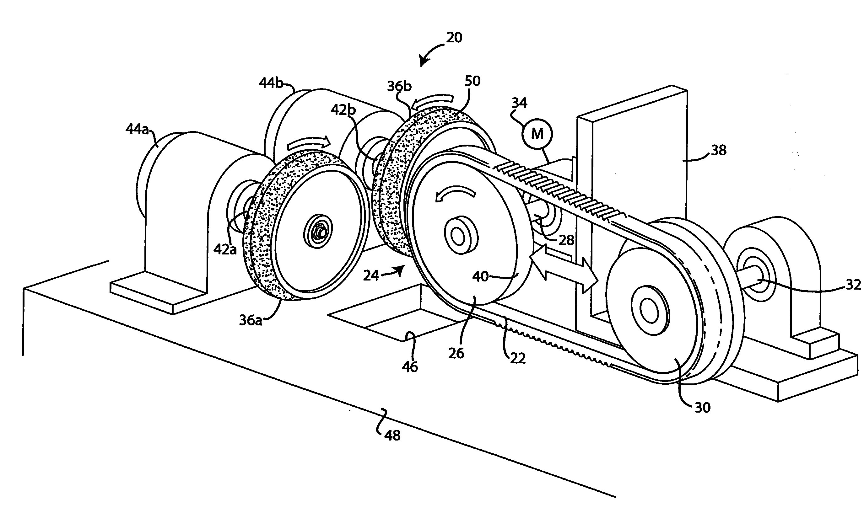
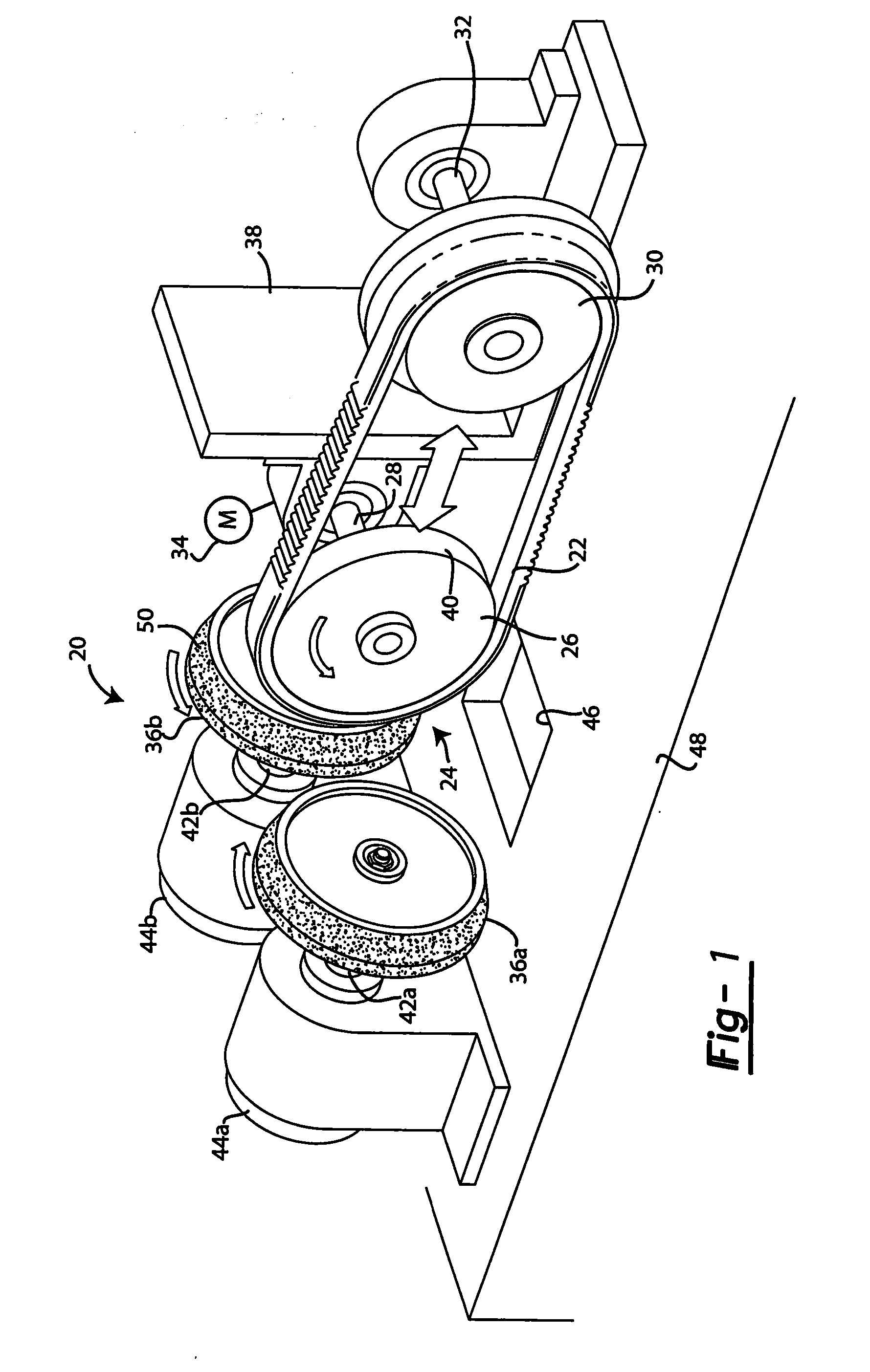
[0028]Referring to FIG. 1, a grinding apparatus in accordance with the present disclosure is illustrated at 20. The workpiece belt to be processed is shown at 22, mounted on a moving anvil system 24. The moving anvil system includes an anvil wheel 26 journaled for rotation about shaft 28 and take-up wheel 30, journaled for rotation about shaft 32. Shaft 28 is driven for rotation by a motor shown diagrammatically in FIG. 1 at 34. The direction rotation is such that the belt 22 moves downwardly into the path of the grinding wheels 36a and 36b.

[0029]The take-up wheel 30 of the moving anvil system is preferably disposed on a repositionable, sliding carriage 38 that allows the take-up wheel to be moved both closer and farther from the anvil wheel. The sliding carriage 38 thus allows the belt 22 to be installed on the respective anvil and take-up wheels and then stretched to tighten, ensuring that the belt is held firmly on the anvil wheel during grinding. The anvil wheel 26 and the take...

third embodiment

[0038]In a third embodiment shown in FIG. 6c, the angle or contour of the belt is defined in part by the acute angle 60c of the grinding wheel surface 50 and also in part by the angle of the wheel's rotational axis 62 relative to the transverse plane 64 of the belt.

[0039]The embodiment of FIG. 6a is presently preferred from an equipment manufacturing standpoint. This is because the embodiment of FIG. 6a spins the grinding wheels about rotational axes 62 that are perpendicular to the transverse plane 64 of the belt. Thus, in this embodiment, as seen in FIG. 1, the two grinding wheels 36a and 36b are situated with their rotational axes parallel with both axes being perpendicular to the rotational axis of the anvil wheel 26. Because parallel and perpendicular geometries are used in this embodiment, alignment of the grinding wheels and anvil can be effected using straightforward 90° alignment fixtures.

[0040]In each of the above embodiments the anvil wheel has a round or circular cross s...


PUM

PropertyMeasurementUnit
Angleaaaaaaaaaa
Radiusaaaaaaaaaa

Abstract

The V-belt is produced with inwardly tapered sidewalls using an apparatus having at least one motorized cutting wheel having first axis of rotation and a moving anvil system with an anvil wheel having a second axis of rotation not parallel to the first axis. The anvil system is motorized and situated so the workpiece follows a U-shaped trajectory into the path of the cutting wheel. The circumferential gripping surface of the anvil wheel and circumferential cutting surface of the cutting wheel are geometrically arranged so that at the point of contact between workpiece and cutting wheel the respective surfaces define planes that intersect in an acute angle that defines the inwardly tapered sidewalls.

Description

FIELD[0001]The present disclosure relates generally to the manufacture of V-belts. More particularly, the disclosure relates to the manufacture of V-belts using an abrading or grinding apparatus.BACKGROUND[0002]This section provides background information related to the present disclosure which is not necessarily prior art.[0003]V-belts find utility in a wide range of applications where it is desired to transmit motive power between rotating shafts. For example, V-belts are widely used in automotive applications. The term “V-belt” derives from the cross-sectional shape of the belt. The V-belt is manufactured to have a pair of inwardly tapered sidewalls that are adapted to fit within the corresponding tapered structure of the pulley onto which the belt is fitted.[0004]V-shaped drive belts have been used in machining, such as manufacturing equipment or mobile vehicles, throughout history. These belts efficiently engage both drive and driver pulleys to transmit torque to various rotata...

Claims


Application Information

Patent Timeline
IPC IPC(8): B24B5/36B29D29/10B24B27/00
CPCB24B27/0076B24B5/36B29D29/10B24B5/50
Inventor SEACHRIST, FRANK
Owner FRICTION COATING
Why Eureka
Try Eureka