
Ultrasonic measuring device, ultrasonic image device, and ultrasonic measuring method

a technology of ultrasonic measurement and ultrasonic image, applied in ultrasonic/sonic/infrasonic image/data processing, mechanical vibration separation, application, etc., can solve problems such as difficult to obtain absolute values, lymphedema, and possible events

Inactive Publication Date: 2015-01-15
SEIKO EPSON CORP
View PDF6 Cites 21 Cited by
  • Summary
  • Abstract
  • Description
  • Claims
  • Application Information

AI Technical Summary

Benefits of technology

The patent proposes an ultrasonic device that can measure the hardness of biological tissue without affecting the sensitivity of ultrasound images. This device can detect abnormalities in the tissue, such as lymphedema, with high precision. Additionally, it can provide accurate thickness information and detect the boundary between different tissue layers with higher accuracy. Overall, this device provides a more efficient and precise tool for diagnostic ultrasonography.

Problems solved by technology

Lymph node dissection has been performed as a treatment of breast cancer, but lymphedema, which may occur as a sequel after the dissection, is becoming a problem.
With this method, it is possible to see the relative difference with respect to the hardness of biological tissue, but this method is problematic in that it is difficult to obtain absolute values, and it is necessary to sacrifice reception sensitivity of the ultrasound image itself because the signal electrode of the ultrasonic vibrator is divided into two.

Method used


Image

  • Ultrasonic measuring device, ultrasonic image device, and ultrasonic measuring method
  • Ultrasonic measuring device, ultrasonic image device, and ultrasonic measuring method
  • Ultrasonic measuring device, ultrasonic image device, and ultrasonic measuring method

Examples


Embodiment Construction

[0032]The following is a detailed description of preferred embodiments of the invention. Note that the embodiments described below are not intended to unduly limit the content of the invention recited in the claims, and all of the configurations described in the embodiments are not necessarily essential as solutions provided by the invention.

[0033]1. Basic Configuration Example

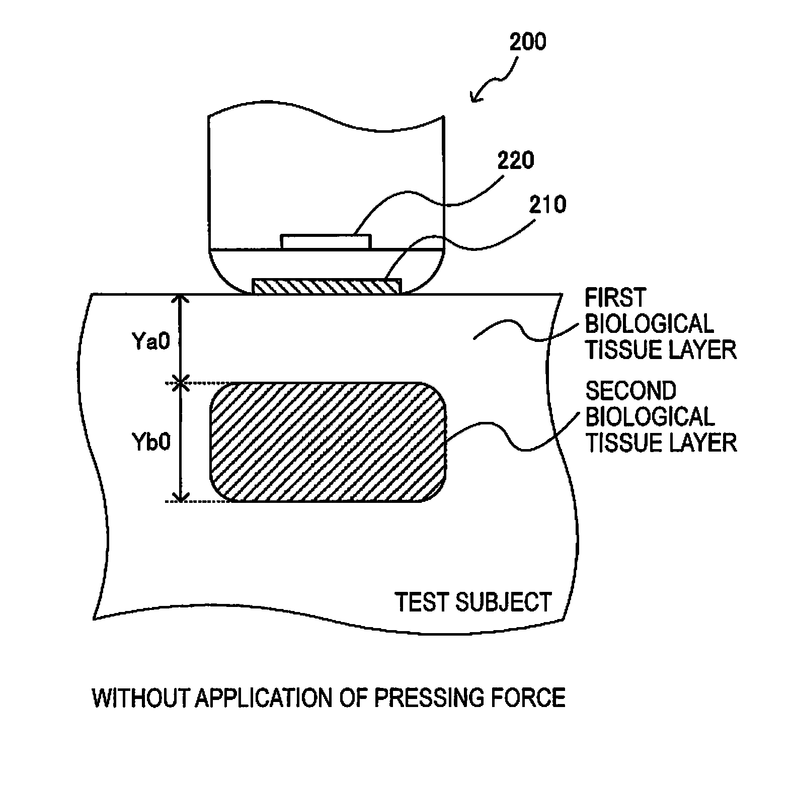
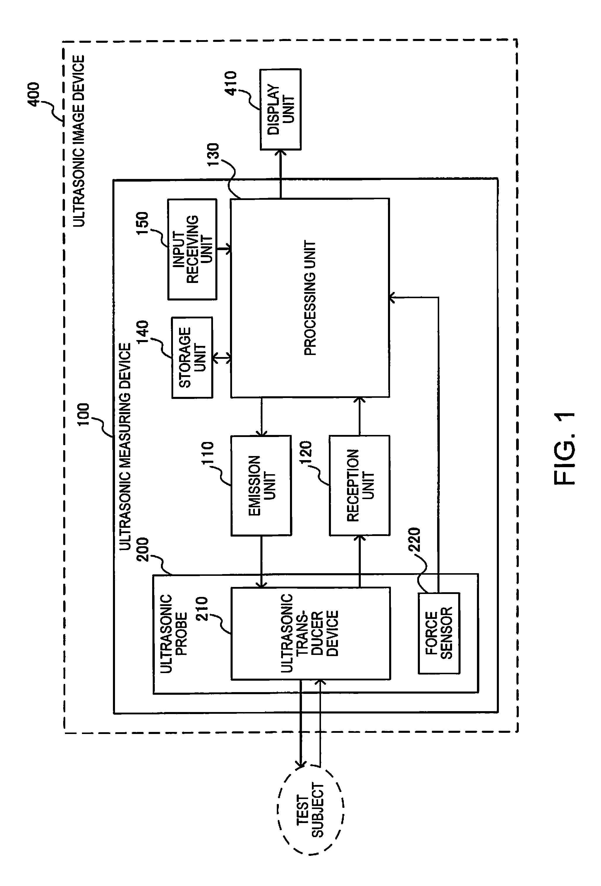
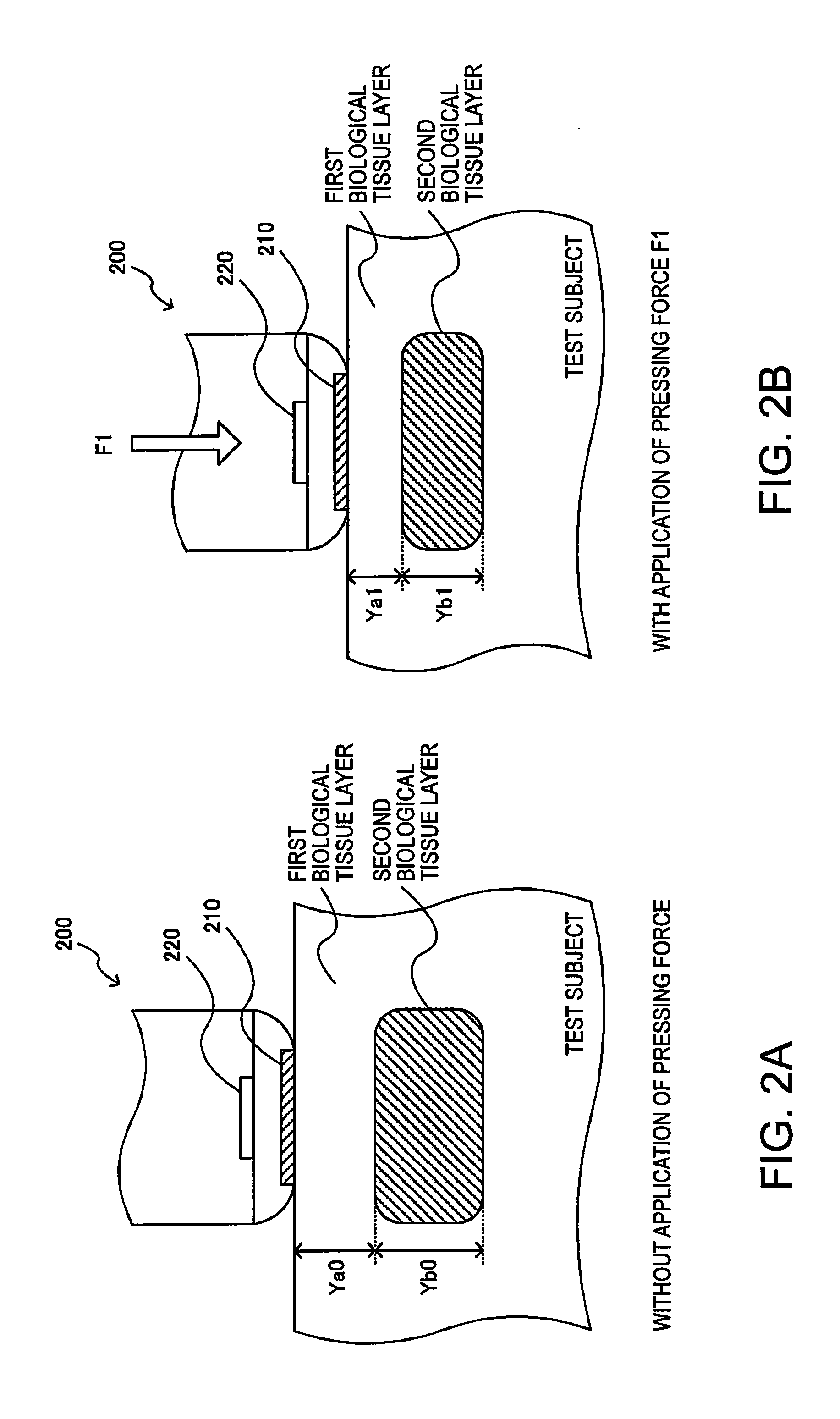
[0034]FIG. 1 shows an example of the basic configurations of an ultrasonic measuring device 100 and an ultrasonic image device 400 of this embodiment. The ultrasonic measuring device 100 of this embodiment includes an ultrasonic probe 200, an emission unit 110, a reception unit 120, a processing unit 130, a storage unit 140, and an input receiving unit 150. The ultrasonic probe 200 includes an ultrasonic transducer device 210 and a force sensor 220. The ultrasonic image device 400 includes an ultrasonic measuring device 100 and a display unit 410. Note that the ultrasonic measuring device 100 and the ultrasoni...


PUM


Abstract

An ultrasonic measuring device including: an ultrasonic transducer device; a force sensor that measures pressing force; an emission unit that performs processing for emitting an ultrasonic beam; a reception unit that performs processing for receiving an ultrasonic echo obtained from the ultrasonic beam being reflected by a test subject; and a processing unit that performs analysis processing based on a reception signal from the reception unit and detection information from the force sensor, wherein the processing unit obtains elasticity information of a biological tissue layer of the test subject based on thickness information and pressing force information, the thickness information being thickness information of the biological tissue layer acquired based on the reception signal from the reception unit, and the pressing force information being pressing force information regarding the pressing force applied to the test subject from the force sensor.

Description

BACKGROUND[0001]1. Technical Field[0002]The present invention relates to an ultrasonic measuring device, an ultrasonic image device, an ultrasonic measuring method, and the like.[0003]2. Related Art[0004]Lymph node dissection has been performed as a treatment of breast cancer, but lymphedema, which may occur as a sequel after the dissection, is becoming a problem. As a method for detecting a lesion, such as lymphedema, that has an elastic constant different from that of normal biological tissue, detecting hardness (elastic constant) of biological tissue is known. For example, JP-A-10-118062 discloses a method in which an ultrasonic vibrator and a frequency measuring unit for detecting a resonance frequency of the ultrasonic vibrator are provided, and the hardness of an object is detected from the measured resonance frequency.SUMMARY[0005]With this method, it is possible to see the relative difference with respect to the hardness of biological tissue, but this method is problematic i...

Claims


Application Information

Patent Timeline
Patent Type & Authority Applications(United States)
IPC IPC(8): A61B8/08A61B5/00
CPCA61B8/485A61B5/418A61B8/4444A61B8/4483A61B8/5207A61B8/0858A61B8/4405A61B8/4427A61B8/4494A61B8/5223B06B1/0629G16H50/30
Inventor ENDO, KOGO
Owner SEIKO EPSON CORP
Learn More