Thin film solar cell and method for manufacturing same

a technology of thin film solar cells and manufacturing methods, which is applied in the direction of photovoltaics, electrical devices, semiconductor devices, etc., can solve the problems of reducing production efficiency and requiring processing time, and achieve the effect of improving production efficiency and easy working process

Inactive Publication Date: 2015-01-22
HONDA MOTOR CO LTD
View PDF6 Cites 7 Cited by
  • Summary
  • Abstract
  • Description
  • Claims
  • Application Information

AI Technical Summary

Benefits of technology

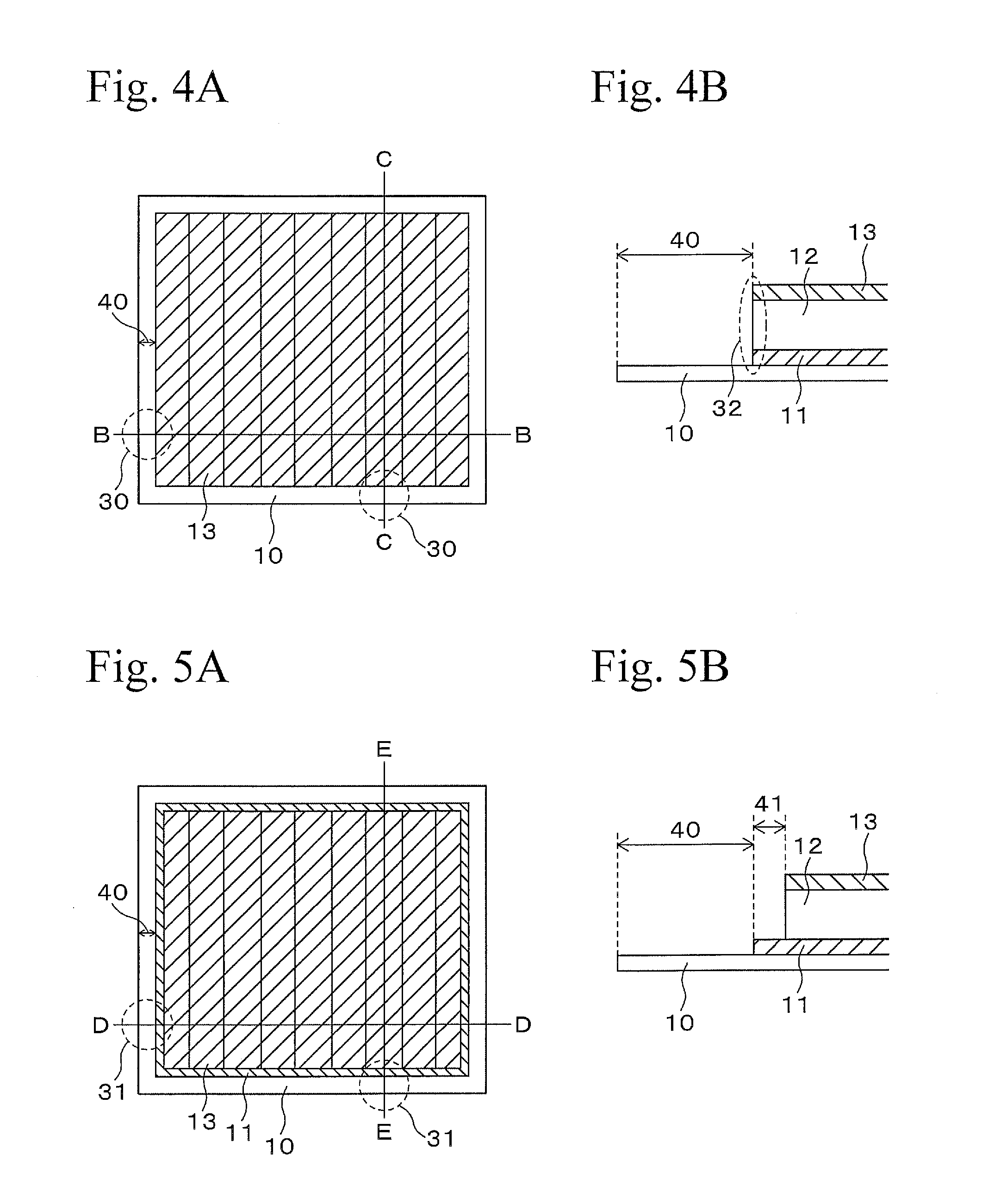
[0014]However, in this method, since the area 41 having a width to some extent should also be removed in addition to the area 40, it may require time for processing, and production efficiency may be decreased.
[0015]The present invention has been completed in view of the above circumstances, and objects of the present invention are to provide a method for producing a thin-film solar cell in which an area of a circumferential part of the thin-film solar cell in which the back surface electrode layer and the transparent electrode layer may short-circuit by heat of a laser beam can be removed from the solar cell element by an easier working process, and to provide a solar cell produced by the method.
[0020]Conventionally, the circumferential part of the thin-film solar cell in which the back surface electrode layer and the transparent electrode layer are short-circuited by influence of heat of a laser beam has been removed by removing an area having a certain width including the part affected by heat; however, in the present invention, the heat affected part can be electrically cut off from the solar cell element only by forming the perpendicular groove having a narrow linear shape, and working process is easy, and thus production efficiency of the thin-film solar cell can be improved.

Problems solved by technology

However, in this method, since the area 41 having a width to some extent should also be removed in addition to the area 40, it may require time for processing, and production efficiency may be decreased.

Method used

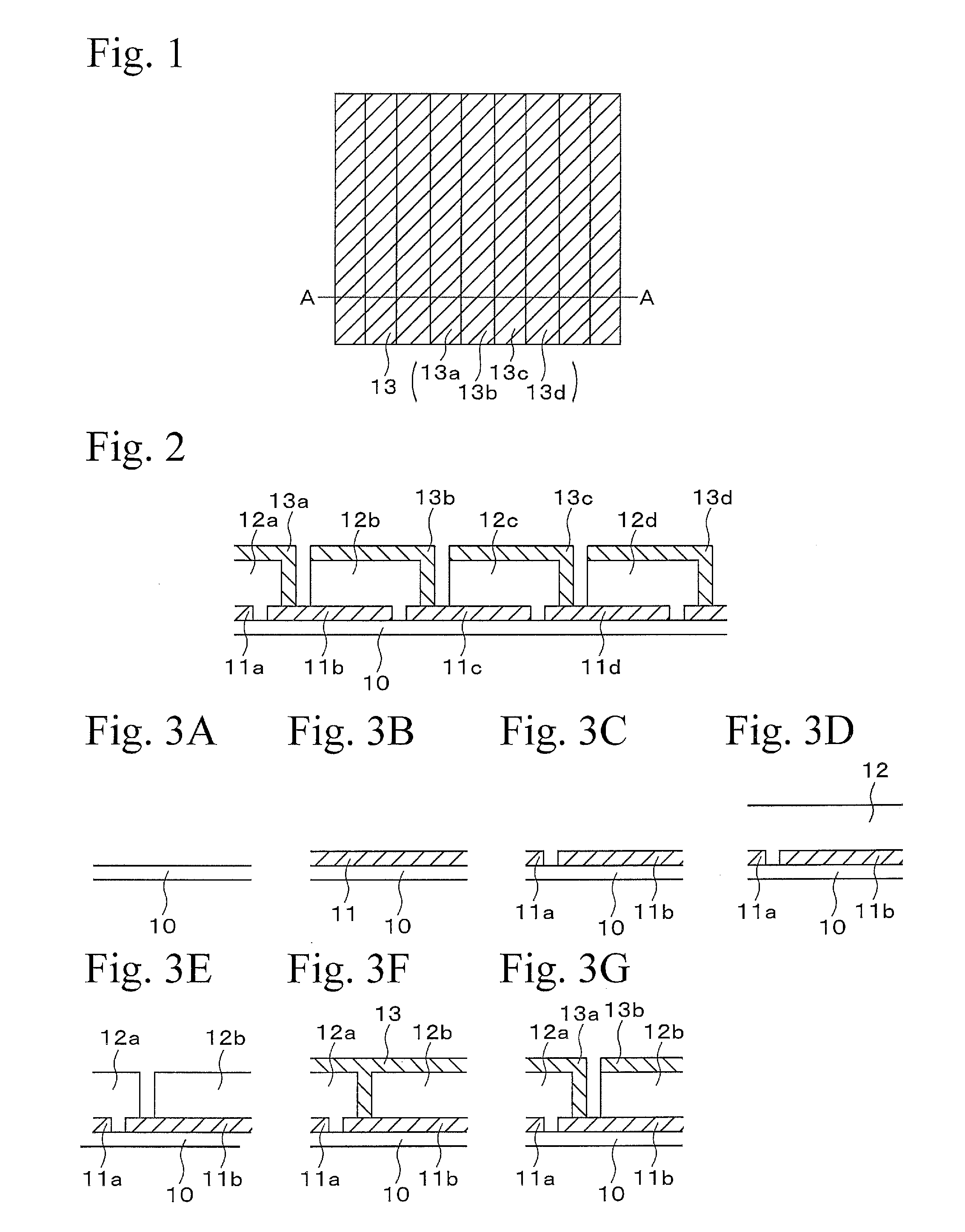

Image

  • Thin film solar cell and method for manufacturing same
  • Thin film solar cell and method for manufacturing same
  • Thin film solar cell and method for manufacturing same

Examples


example 1

[0048]By the method for production mentioned above, a back surface electrode layer having a thickness of 0.4 μm, a light absorbing layer having a thickness of 1.4 μm, and a transparent electrode layer having a thickness of 0.6 μm were formed on a glass substrate, in this order, so as to produce a thin-film solar cell. An area 42 to be removed, which is a circumferential part of the solar cell shown in FIG. 6 was set at 6.4 mm, and this area was removed by a laser having a power output 15 W. Perpendicular grooves are formed at both sides of the solar cell at the heat relaxation distance from the end, so as to obtain the thin-film solar cell of Example 1. It should be noted that the heat relaxation distance 43 was set 100 μm and width 44 of the perpendicular groove 20 was set 40 μm, so as to remain 60 μm to the outside of the perpendicular groove.


PUM


Abstract

A thin-film solar cell includes a substrate, a back surface electrode layer, a light-absorbing layer, and a transparent electrode layer, layered on the substrate, in this order. The layers are divided into multiple unit cells by a scribed groove, and the cells serially connected. At an inside of an end side of the solar cell perpendicular to the scribed groove, a groove is formed perpendicular to the scribed groove and has the back surface electrode is removed therefrom. The thin-film solar cell is produced by emitting a laser beam on the solar cell element of an end part of a side perpendicular to the scribed groove so as to form a new end surface by removing the back surface electrode layer, the light-absorbing layer and the transparent electrode layer, and mechanically forming the perpendicular groove perpendicular to the scribed groove, at inside of the new end surface.

Description

TECHNICAL FIELD[0001]The present invention relates to a method for producing a thin-film solar cell, such as a chalcopyrite-type thin-film solar cell, in which a light-absorbing layer contains a chalcopyrite-based compound, and in particular, relates to a technique to improve power output of the thin-film solar cell,BACKGROUND ART[0002]A solar cell is generally classified as a single-crystal solar cell, a poly-crystal solar cell, a thin-film solar cell, etc. Among these, the thin-film type solar cell has been developed and is commercialized, since it has an advantage in that the amount of raw material used is less than in other types of solar cells for the same power output, and an advantage in that production processing is easier and less energy is required.[0003]A chalcopyrite-type thin-film solar cell, which is a kind of thin-film type solar cell, has a CIGS layer including a chalcopyrite based compound (for example, Cu (In1-xGax)Se2, hereinafter referred to as “CIGS”) as a p-typ...

Claims


Application Information

Patent Timeline
Patent Type & Authority Applications(United States)
IPC IPC(8): H01L31/18H01L31/0224H01L31/05
CPCH01L31/0516H01L31/186H01L31/022441H01L31/0463Y02E10/50
Inventor OYAMA, SATOSHIKUME, TOMOYUKI
Owner HONDA MOTOR CO LTD
Why Eureka
Try Eureka