Interfacing Capillary Electrophoresis to a Mass Spectrometer via an Impactor Spray Ionization Source

a mass spectrometer and impactor technology, applied in the direction of particle separator tube details, instruments, separation processes, etc., can solve the problems of imposing limitations on buffer concentration and esi voltage stability, and the additional cost of esi power supply circuits, so as to improve the interfacing effect and simplify the interfacing ms sour

Active Publication Date: 2015-01-22
MICROMASS UK LTD
View PDF0 Cites 37 Cited by
  • Summary
  • Abstract
  • Description
  • Claims
  • Application Information

AI Technical Summary

Benefits of technology

[0019]The preferred embodiment alleviates interfacing problems by decoupling the ionizing high voltage from the probe tip and instead preferably utilizing a grounded probe assembly which acts as a stable reference for the applied CE voltage. In impactor Spray ionization, the nebuliser probe tip is preferably held at ground potential whilst any high voltage for ionization is preferably held on an impactor target that is preferably positioned a short distance from the

Problems solved by technology

Another disadvantage of the conventional arrangement is that biasing the ESI tip requires the additional cost of an ESI po

Method used


Image

  • Interfacing Capillary Electrophoresis to a Mass Spectrometer via an Impactor Spray Ionization Source
  • Interfacing Capillary Electrophoresis to a Mass Spectrometer via an Impactor Spray Ionization Source

Examples


Embodiment Construction

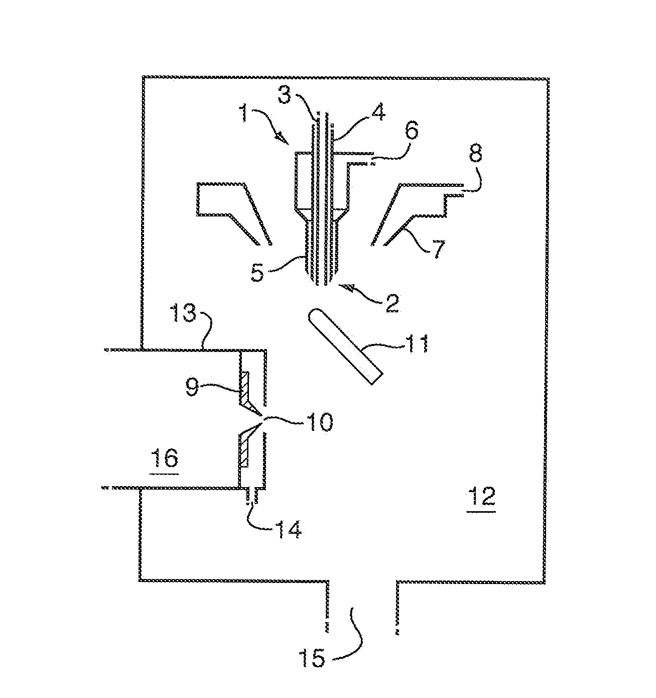
[0107]FIG. 1 is a schematic of the general layout of an impactor spray API source according to a preferred embodiment. A flow of liquid from a CE column outlet (or other separation device) enters a nebuliser probe 1 and is delivered to a sprayer tip 2 via an inner capillary tube 3. The inner capillary 3 is surrounded by a second concentric capillary 4 which delivers a make-up flow of liquid which mixes with the flow from the first capillary 3 at the probe tip. The second capillary tube 4 is surrounded by a third concentric capillary 5 which includes a gas inlet 6 to deliver a stream of high velocity gas to the exit of the liquid capillaries 3,4.

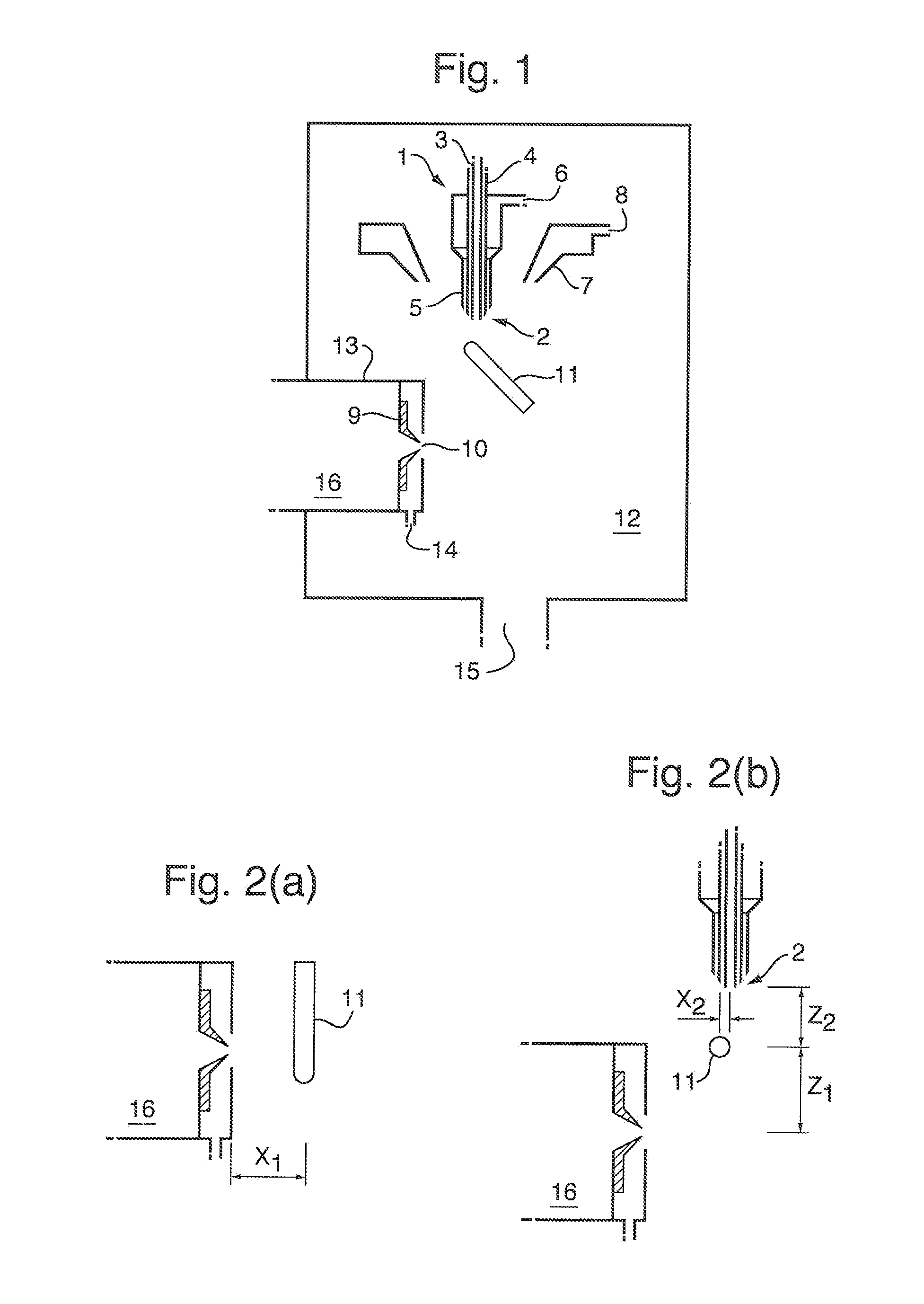
[0108]This arrangement produces a nebulised spray which contains droplets with a typical diameter of 10-20 μm and velocities greater than 100 m / s at a close distance from the sprayer tip 2. The resulting droplets are heated by an additional flow of gas that enters a concentric annular heater 7 via a second gas inlet 8.

[0109]The sprayer is pre...


PUM


Abstract

A mass spectrometer is disclosed comprising a separation device arranged and adapted to emit an eluent over a period of time. The separation device preferably comprises a Capillary Electrophoresis (“CE”) separation device. The mass spectrometer further comprises a nebuliser and a target. Eluent emitted by the separation device is nebulised, in use, by the nebuliser wherein a stream of analyte droplets are directed to impact upon the target so as to ionise the analyte to form a plurality of analyte ions.

Description

CROSS-REFERENCE TO RELATED APPLICATION[0001]This application claims priority from and the benefit of U.S. Provisional Patent Application Ser. No. 61 / 580,558 filed on 27 Dec. 2011, U.S. Provisional Patent Application Ser. No. 61 / 601,827 filed on 22 Feb. 2012, U.S. Provisional Patent Application Ser. No. 61 / 718,836 filed on 26 Oct. 2012, United Kingdom Patent Application No 1122218.9 filed on 23 Dec. 2011, United Kingdom Patent Application No. 1202892,4 filed on 21 Feb. 2012 and United Kingdom Patent Application No. 1219217.5 filed on 25 Oct. 2012. The entire contents of these applications are incorporated herein by reference.BACKGROUND TO THE PRESENT INVENTION[0002]Capillary Electrophoresis (CE) is a separation technique where a high voltage is applied to the sample inlet end of a glass capillary column and a lower voltage, or voltage of opposite polarity, is applied to the outlet end of the capillary. Analytes elute from the column at a rate that is determined by a combination of el...

Claims


Application Information

Patent Timeline
IPC IPC(8): H01J49/04H01J49/10H01J49/00
CPCH01J49/045H01J49/0031H01J49/10H01J49/14H01J49/16H01J49/0454G01N27/4473G01N30/724G01N27/623H01J49/0431G01N30/7266G01N27/44704H01J49/165G01N27/447
Inventor BAJIC, STEVAN
Owner MICROMASS UK LTD
Why Eureka
Try Eureka