LED lighting engine adopting an icicle type diffusion unit

a technology of diffusion unit and led lighting, which is applied in the direction of lighting and heating equipment, instruments, condensers, etc., can solve the problems of insufficient replacement of led lighting devices for conventional lighting sources, and insufficient light control efficiency of led lighting devices. , to achieve the effect of improving light uniformity and light control efficiency per unit area, enhancing surface light sources, and expanding diffusion angles

Active Publication Date: 2015-01-22
HYUN DONG HOON +1
View PDF5 Cites 6 Cited by
  • Summary
  • Abstract
  • Description
  • Claims
  • Application Information

AI Technical Summary

Benefits of technology

[0018]According to the present invention, it is possible to improve a light uniformity and light control efficiency per unit area and to enhance the characteristic of the surface light source so as to further expand a diffusion angle, and the brightness of the light emitting surface for the divergent light of the LED light emitting body is entirely and identically adjusted so as to improve a glare phenomenon, to remove light pollution, and to remove a pattern which may be generated by a pattern of the LED light emitting body.
[0019]According to the present invention, the LED lighting source with the characteristic of the surface light source is integrally coupled with the icicle type diffusion unit so as to provide a sealed structure with a waterproof function and a dustproof function. Accordingly, there are advantages in that lighting efficiency can be improved compared with the conventional lighting, and a cost can be reduced, and that the LED light source can be applied to various fields.
[0020]The present invention can satisfy quality and price of the LED lighting which are the largest variables considered by a user, and can reduce a manufacturing cost considered by a manufacturer. Further, the conventional light source with various market influence powers can be substituted with the LED lighting at a ratio of one to one. Furthermore, the light uniformity and the light diffusion angle can be simply and freely adjusted.

Problems solved by technology

However, actual counterplans of related enterprises and related markets which have no basic knowledge for the conventional lighting device have failed to satisfy expectation.
With relation to a price to which a market attaches a great importance, especially, in the case in which it is desired that an LED lighting device be substituted for a conventional lighting device, since the price of the LED lighting device is at least five times to at most twenty times higher than the conventional lighting device, it is very insufficient to substitute the LED lighting device for the conventional lighting source.
However, a market and a user are actually indifferent to the LED lighting device and expect that the price of the LED lighting device will be lowered.
Although it is clear that some newer enterprises have made efforts to lower the price of the LED lighting device, quality of the lighting source is deteriorated and a new side effect named ‘light pollution’ is caused as the price of the LED lighting device is lowered.
Further, in the case that the LED lighting device is conventionally applied as scenery lighting, the scenery lighting can be viewed only in front of the LED lighting device because of the linearity of light emitted from the LED lighting device, but an image such as an advertisement cannot be seen at a side of the scenery lighting at all because it is dark.
Accordingly, there is a problem in that it is difficult to control light, and there is inconvenience caused by glare and light pollution.
In addition, in the case that the conventional LED lighting device is applied as a backlight to a television and the like, in which an edge emission is applied to a television with a size smaller than 52 inches and a direct emission is applied to a television with a size larger than 60 inches, there are problems in that the price of the backlight increases and also quality of the lighting in the backlight is deteriorated.

Method used


Image

  • LED lighting engine adopting an icicle type diffusion unit
  • LED lighting engine adopting an icicle type diffusion unit
  • LED lighting engine adopting an icicle type diffusion unit

Examples


Embodiment Construction

[0051]Hereinafter, preferred embodiments of the present invention will be described in detail with reference to the accompanying drawings, and the aspects, configurations and features of the present invention will be more appreciated through the following description.

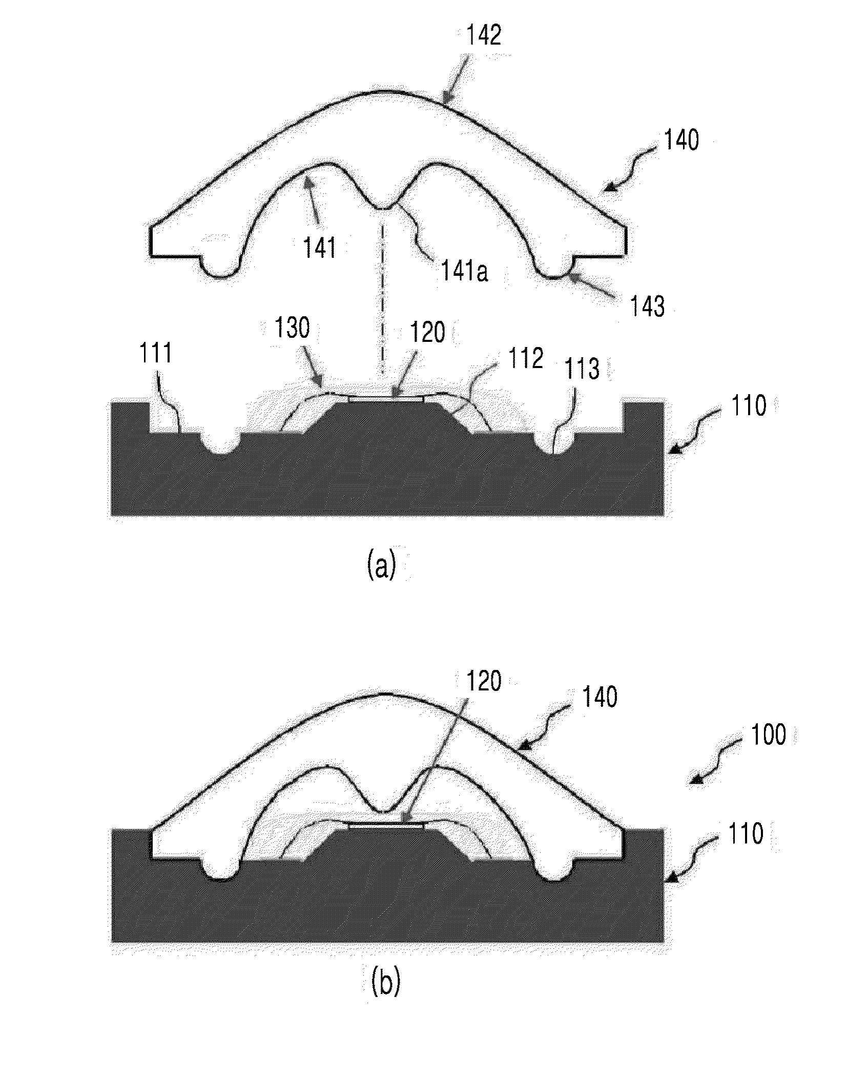
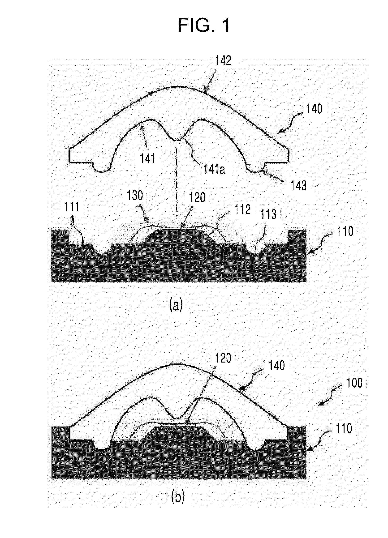
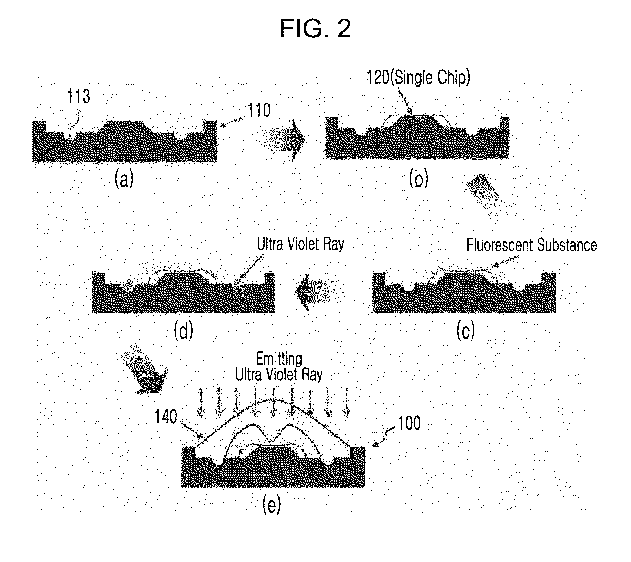
[0052]As shown in FIGS. 1 and 2, an LED lighting engine 100 adopting an icicle type diffusion unit according to an embodiment of the present invention includes a substrate 110, an LED light emitting body 120, a fluorescent substance 130, and the icicle type diffusion unit 140.

[0053]The substrate 110 is a chip on board (COB) on which the LED light emitting body 120 is mounted and electrically connected, and which is to radiate heat of the LED light emitting body 120. The substrate 110 is preferably constituted of a printed circuit board (PCB) made from a metal such as an aluminum material and the like, or a PCB made from a thermally conductive material such as a thermally conductive plastic.

[0054]At this time, the substr...


PUM

PropertyMeasurementUnit
sizeaaaaaaaaaa
sizeaaaaaaaaaa
thermal conductiveaaaaaaaaaa

Abstract

Disclosed is an LED lighting engine adopting an icicle type diffusion unit. The LED lighting source having a surface light source characteristic and an icicle type diffusion unit corresponding to the surface light source are integrally formed through coupling therebetween to provide a shield type structure having waterproof and dustproof functions. Also, the LED lighting engine may improve lighting efficiency and reduce manufacturing costs when compared to an existing lighting device, and may also be applied in various ways. Also, the LED lighting engine may satisfy quality and pricing standards for LED lighting which are the main variables visible to the eyes of a user. In addition, the LED lighting engine may be simply replaced with conventional LED lighting in a one-on-one ratio (size) which greatly influences market competitiveness. Also, the LED lighting engine may be simply and freely adjusted in terms of light uniformity and light diffusion angle.

Description

TECHNICAL FIELD[0001]The present invention relates to a lighting engine having a Light Emitting Diode (LED) adopted thereto, and more particularly to an LED lighting engine adopting an icicle type diffusion unit, in which a specific LED light emitting body with a characteristic of a surface light source is adopted as a basic element in order to improve a light uniformity and efficiency per unit area, and which is capable of performing a double light diffusion treatment using total internal reflection and refraction, improving a glare phenomenon and removing a light pollution by entirely and identically adjusting a brightness of a light emitted surface for divergent light of the LED light emitting body, removing an occurrence of a pattern caused by a light emitting body, and efficiently controlling the light.BACKGROUND ART[0002]Recently, use of an LED light emitting body as a light source has been increased throughout many industries including a lighting device industry. Thus, resear...

Claims


Application Information

Patent Timeline
Patent Type & Authority Applications(United States)
IPC IPC(8): F21V29/00F21V7/00F21V17/02F21K99/00F21V5/04H01L33/50
CPCF21V5/04F21K9/50F21V29/22F21Y2101/02H01L33/50F21V7/0091F21V17/02F21V3/02F21V3/0436F21W2121/006F21Y2105/008G02B19/0028G02B19/0061H01L33/58H01L51/5268H01L2224/48091H01L2224/8592H01L2251/5361H01L2933/0058H01L2924/12044F21V29/70F21Y2105/00F21K9/60F21Y2115/15F21Y2115/10F21V3/062H10K50/854H01L2924/00014H01L2924/00
Inventor HYUN, DONG HOONNOH, MYEUNG JAE
Owner HYUN DONG HOON
Why Eureka
Try Eureka