Control device of a switching power supply

Inactive Publication Date: 2015-01-22
FUJI ELECTRIC CO LTD
View PDF8 Cites 11 Cited by
  • Summary
  • Abstract
  • Description
  • Claims
  • Application Information

AI Technical Summary

Benefits of technology

[0021]The present invention has been made in view of the situation and an object of the present invention is to provide a control device of a switching po

Problems solved by technology

As a result, the output voltage scarcely changes, which means control of the output voltage is virtually impossible.
As a result, when a setting value of output voltage is changed, the output voltage varies slowly to the new output voltage value in the range of low output voltages, but in the range of high output voltages, the output voltage varies abruptly causing overshooting, which may subject the load to an overvoltage and sometimes destroy the lo

Method used


Image

  • Control device of a switching power supply
  • Control device of a switching power supply
  • Control device of a switching power supply

Examples


first embodiment

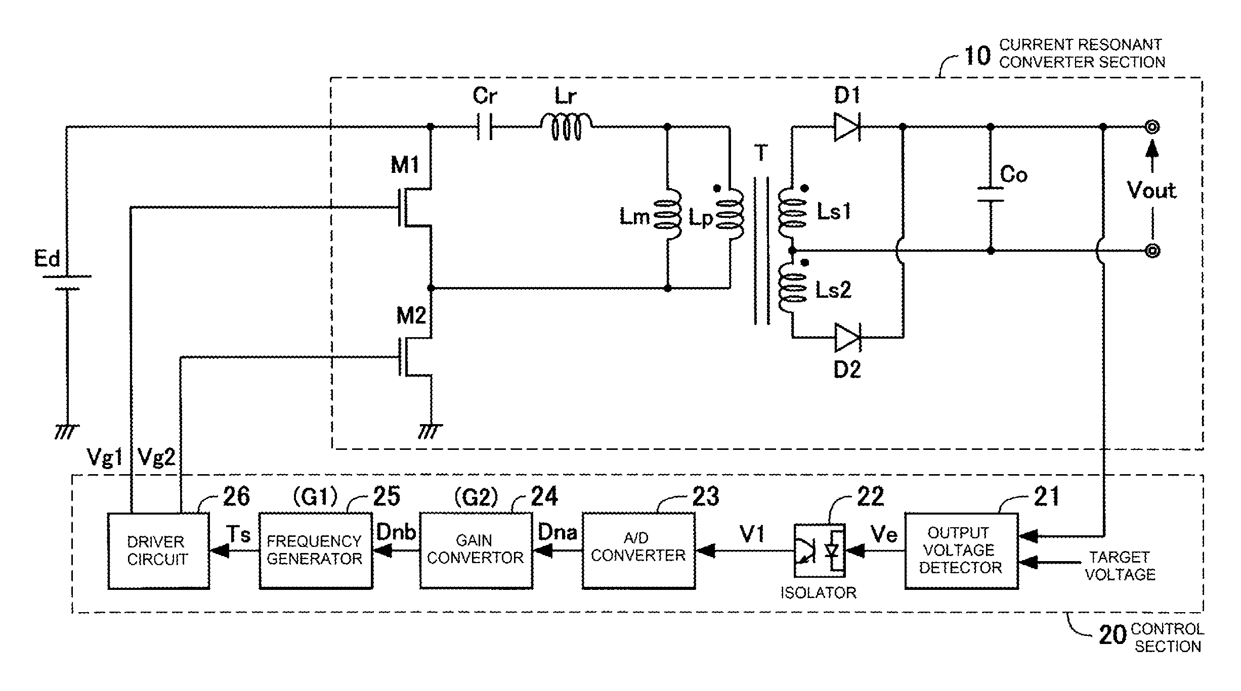
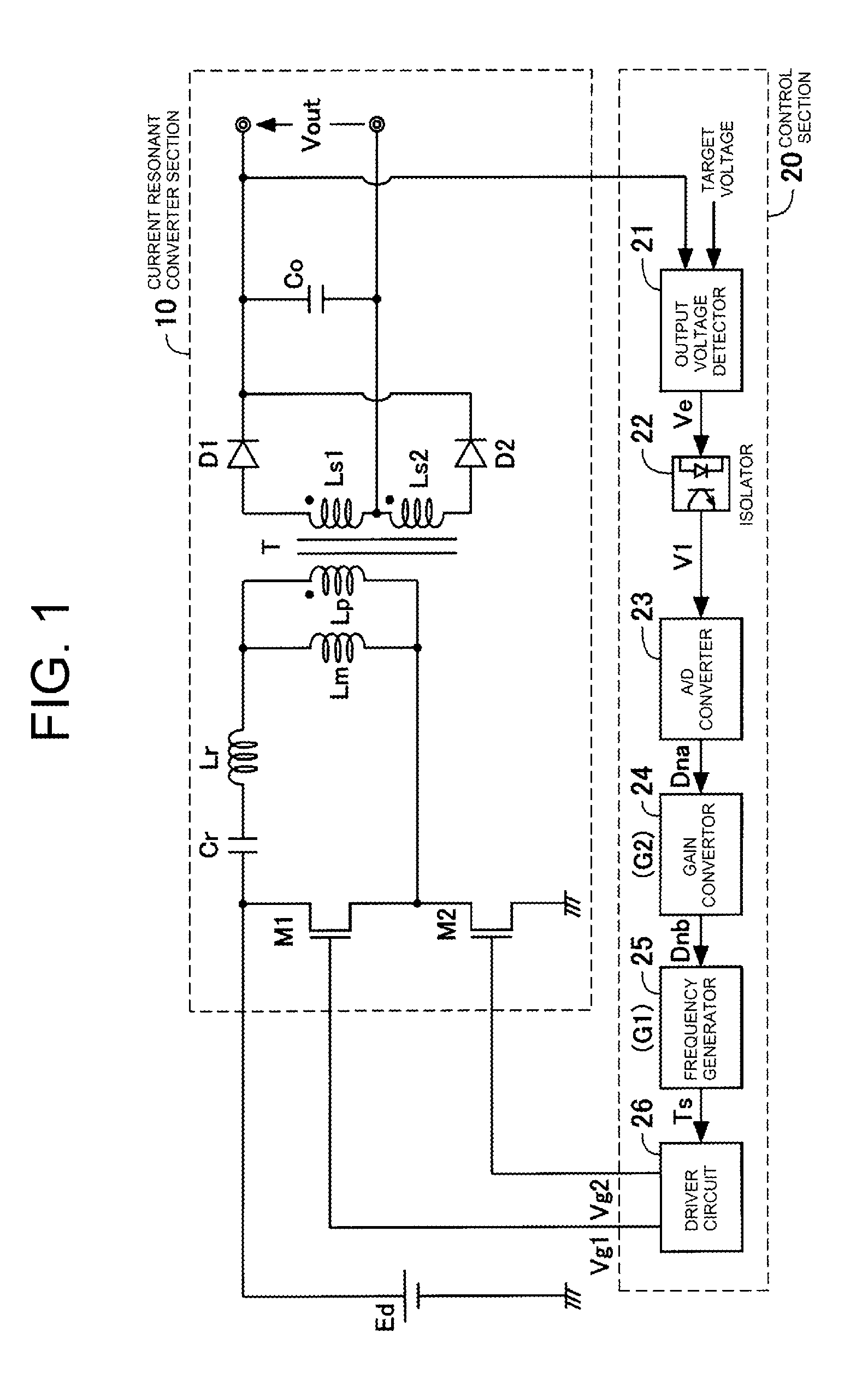
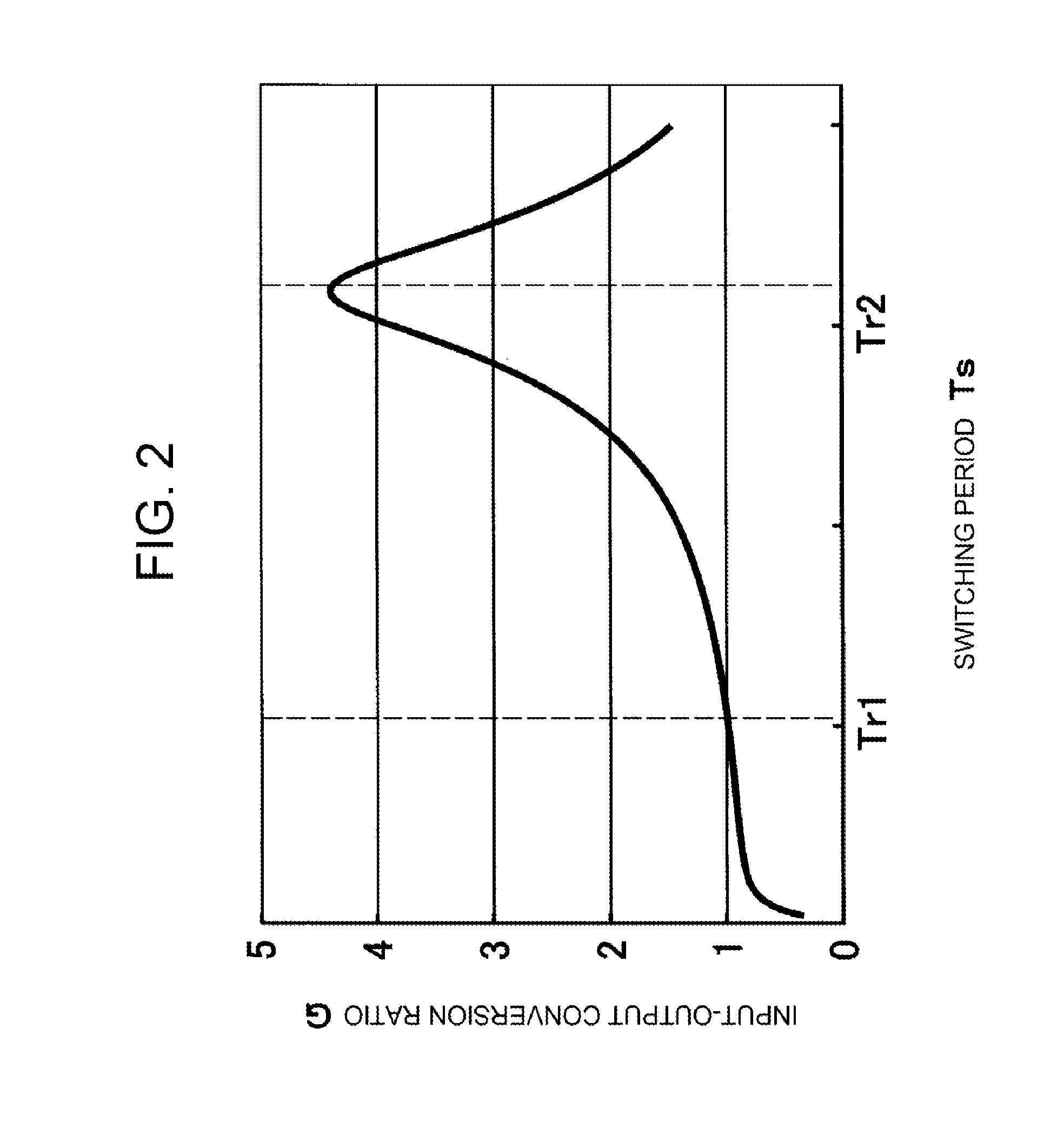
[0037]FIG. 1 shows an example of construction of a current resonant converter to which a control device of a switching power supply according to the present invention is applied. FIG. 2 shows an input-output characteristic, switching period dependence of input-output conversion ratio, of a current resonant converter section.

[0038]The current resonant converter having the construction of FIG. 1 comprises a current resonant converter section 10 and a control section 20. The current resonant converter section 10 includes two switching elements M1 and M2 connected in series, to which a DC input power supply is connected and an input voltage Ed is applied. The switching element M1 is connected in parallel with a series circuit of a resonant capacitor Cr, a resonant inductance Lr, and a magnetizing inductance Lm. The magnetizing inductance Lm is connected in parallel with a primary winding Lp of a transformer T. The transformer T has secondary windings Ls1 and Ls2 provided with a center t...

second embodiment

[0075]FIG. 9 shows an example of construction of a current resonant converter to which a control device of a switching power supply according to the present invention is applied.

[0076]The control section 20 of this second embodiment uses an isolation amplifier for an isolator 22 to transmit a signal from the secondary side to the primary side of the transformer T, and a DC output voltage Vout of the current resonant converter section 10 is directly given to the isolator 22. An output voltage detector 21 receives the output signal from the isolator 22 and delivers an error signal Ve with respect to a target voltage. The output signal of the output voltage detector 21 is given to an A-D converter 23, where an analog quantity of the error signal Ve is converted into a digital signal De. The output of the A-D converter 23 is given to a digital calculator 27, where control calculation is executed to converge the DC output voltage Vout to a setting value of the output voltage. The digital...


PUM


Abstract

A control section for a current resonant converter section controls a DC output voltage of a current resonant converter section to settle to a target voltage by varying a resonant period between predetermined two resonant periods based on an error signal between the DC output voltage and the target voltage. A gain converter is provided in a preceding stage of a frequency generator for generating a square waveform signal with a duty ratio of 50% and the gain converter has a setting of a nonlinear gain characteristic that cancels nonlinearity in the input-output characteristics of the current resonant converter section. The nonlinear gain characteristic can be a characteristic of continuous gain conversion or discrete gain conversion.

Description

CROSS-REFERENCE TO RELATED APPLICATION[0001]This application is based on, and claims priority to, Japanese Patent Application No. 2013-148197, filed on Jul. 17, 2013, contents of which are incorporated herein by reference.BACKGROUND OF THE INVENTION[0002]1. Field of the Invention[0003]The present invention relates to a control device of a switching power supply, and in particular to improvement of stability of an output voltage in a process of change in a setting value of the output voltage setting in a current resonant converter, a type of switching power supply.[0004]2. Description of the Related Art[0005]Current resonant type converters have been used for high efficient switching power supplies with reduced energy losses. A conventional current resonant converter has a construction described in the following.[0006]FIG. 10 shows an example of construction of a conventional current resonant converter. FIG. 11 shows an input-output characteristic, a switching frequency dependence of...

Claims


Application Information

Patent Timeline
IPC IPC(8): H02M3/335
CPCH02M3/33546H02M2001/0025H02M3/33553H02M1/0025H02M3/01H02M3/33571Y02B70/10Y02P80/10H02M3/33515H02M3/3353H02M1/0058
Inventor KAWASHIMA, TETSUYA
Owner FUJI ELECTRIC CO LTD
Why Eureka
Try Eureka