
ejector

a technology of ejector and outlet part, which is applied in the direction of circuit elements, non-positive displacement pumps, thin material processing, etc., can solve the problems of shock wave, insufficient expansion of ejecting fluid from the outlet part, and dramatic deceleration of accelerated fluid

Active Publication Date: 2015-01-22
DENSO CORP
View PDF2 Cites 9 Cited by
  • Summary
  • Abstract
  • Description
  • Claims
  • Application Information

AI Technical Summary

Benefits of technology

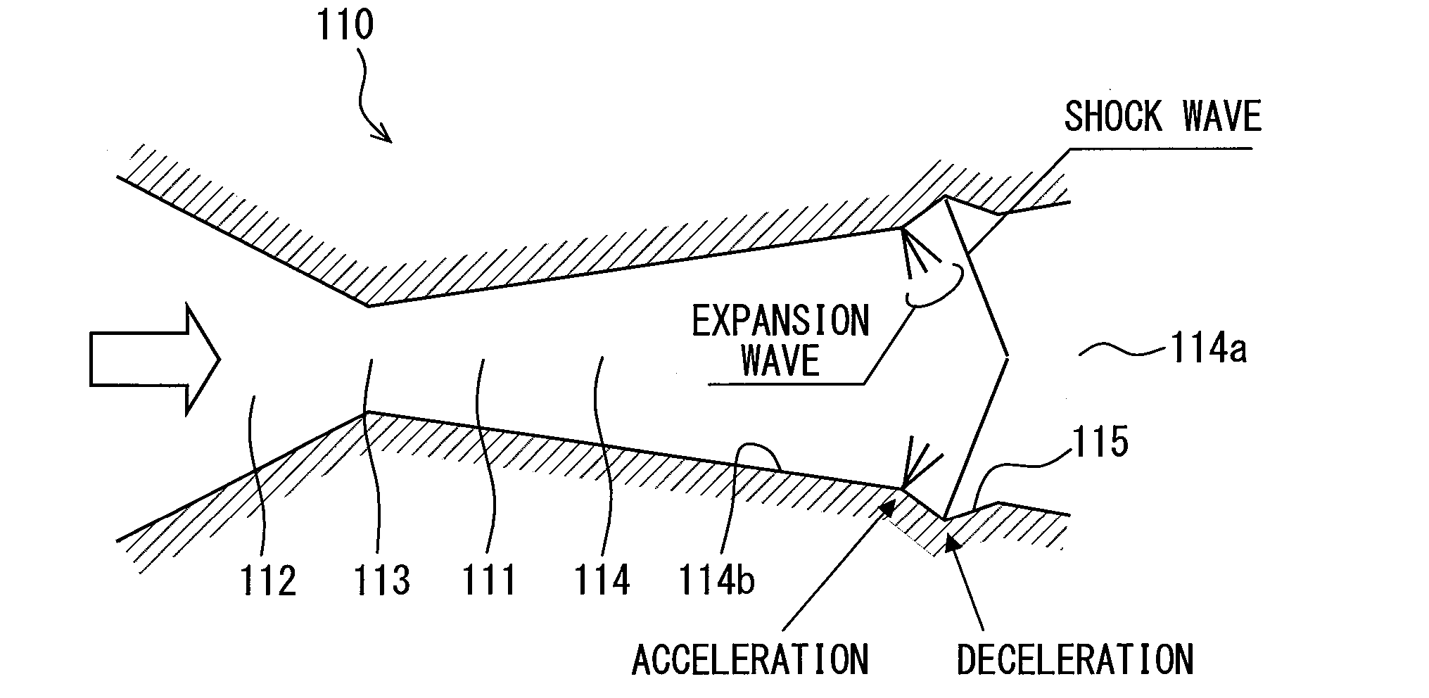
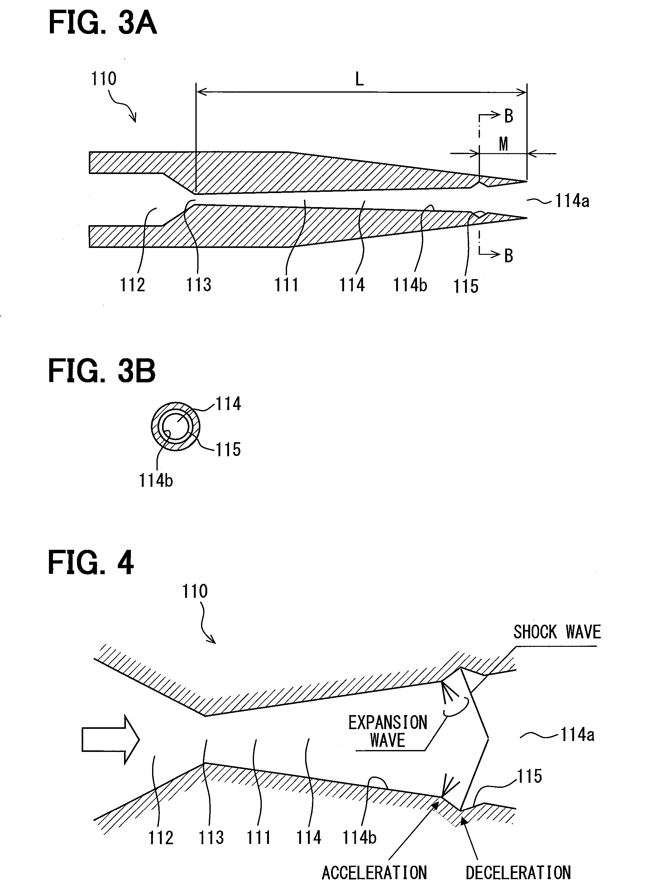
The present invention is about reducing noise caused by an expansion wave of ejected fluid. It achieves this by designing an ejector with a recess portion that has a V-shaped sectional shape. This results in a constant acceleration and deceleration effect of the fluid in the upstream and downstream parts of the recess portion, respectively. The ejector prevents the generation of noise by preventing an expansion wave in the ejected flow and keeps it in an appropriately expanded state or an excessively expanded state. Overall, the invention reduces noise and improves the efficiency of the ejector.

Problems solved by technology

However, according to a study of the inventors of the present application, in the ejector of Patent Document 1, when a flow rate of the fluid flowing into the ejector changes, for example, when the flow rate increases, the fluid ejected from the outlet part may be in an insufficiently expanded state.
Thus, the accelerated fluid is decelerated drastically and causes a shock wave.

Method used


Image

  • ejector
  • ejector
  • ejector

Examples


Embodiment Construction

[0022]Hereinafter, an embodiment for implementation of the present disclosure will be described with reference to the drawings.

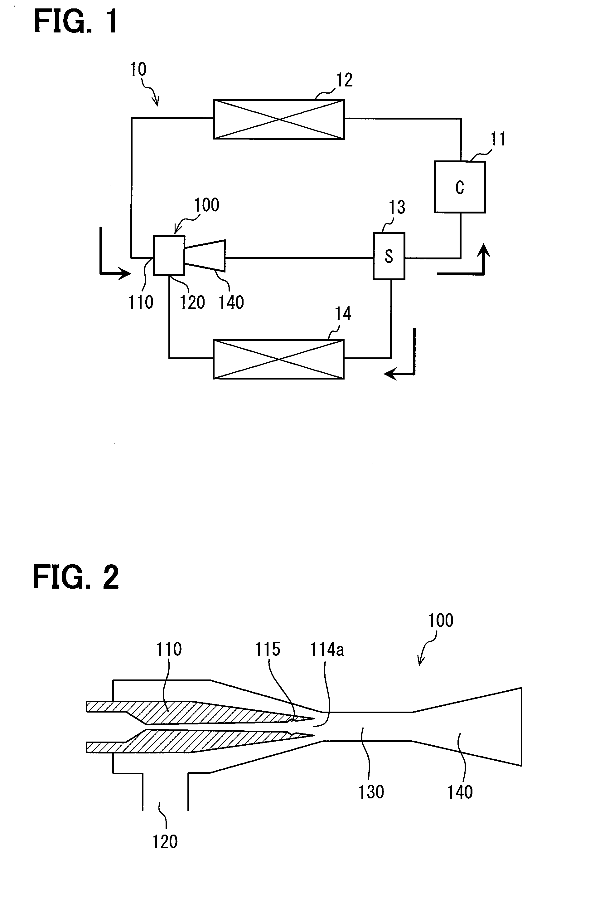
[0023]In FIG. 1, an ejector 100 of the embodiment is used for a vapor-compression refrigeration cycle 10 (hereinafter, refrigeration cycle). The refrigeration cycle 10 is disposed in a vehicle for an air conditioner, in which a compressor 11, a condenser 12, the ejector 100, a gas-liquid separator 13 and an evaporator 14 are connected by a refrigerant pipe. An operation of the compressor 11 is controlled by a non-shown controller, and a refrigerant circulates in the refrigeration cycle 10. The refrigerant may be used as an example of a fluid flowing through the ejector 100.

[0024]The compressor 11 is a fluid machine that draws a gas refrigerant from the gas-liquid separator 13 and compresses the refrigerant into a high-pressure and high-temperature state, thereby discharging the refrigerant to the condenser 12. The compressor 11 is rotary-driven by a vehicle-...


PUM


Abstract

An ejector includes a nozzle having a fluid passage circular in cross section. The fluid passage includes a throat portion smallest in cross-sectional area, a divergent portion that becomes larger in cross-sectional area toward a downstream side from the throat portion, and an ejection port that is provided at a downstream end of the divergent portion. A passage wall surface of the divergent portion includes a recess portion that is recessed from within outward in a radial direction of the passage wall surface. The recess portion is located adjacent to the ejection port, and the recess portion extends continuously in a circumferential direction of the passage wall surface to enclose the fluid passage and have an annular shape. Accordingly, noise due to an expansion wave of the ejected fluid can be reduced.

Description

CROSS REFERENCE TO RELATED APPLICATION[0001]This application is based on and incorporates herein by reference Japanese Patent Application No. 2012-050830 filed on Mar. 7, 2012.TECHNICAL FIELD[0002]The present disclosure relates to an ejector that is a momentum transport pump depressurizing a fluid and transporting the fluid by a suction action of a working fluid ejected at high speed.BACKGROUND ART[0003]An ejector shown in Patent Document 1, for example, is known as a conventional ejector. In the ejector of Patent Document 1, a nozzle includes a throat portion most-reduced in passage cross-sectional area, and a divergent portion enlarged in passage cross-sectional area toward a downstream side from the throat portion. The divergent portion has a middle part on an upstream side, and an outlet part on a downstream side.[0004]A divergent angle θ1 of a passage wall surface of the middle part is configured to be constant within the middle part. A divergent angle θ2 of a passage wall surf...

Claims


Application Information

Patent Timeline
Patent Type & Authority Applications(United States)
IPC IPC(8): F04F5/20F04F5/50
CPCF04F5/50F04F5/20F04F5/16F04F5/24Y10T137/2224F04F5/463F04F5/46
Inventor YAMADA, ETSUHISANISHIJIMA, HARUYUKI
Owner DENSO CORP
Learn More