Congestion control enforcement in a virtualized environment

Active Publication Date: 2015-01-29
MELLANOX TECHNOLOGIES LTD
View PDF8 Cites 51 Cited by
  • Summary
  • Abstract
  • Description
  • Claims
  • Application Information

AI Technical Summary

Benefits of technology

[0036]An additional aspect of the method includes delaying transmission of t

Problems solved by technology

When performing network communication, there can be congestion in the network.
In the event of such congestion, network switches can buffer the traffic up to a limit, after which they either cause backpressure or drop part of the traffic.
Both of these actions can harm performance—dropping traffic will cause a retransmission, while applying backpressure and stopping the originating switch will cause congestion to spread, possibly slowing down the entire network.
The congestion control protocols mentioned above assume that all parties are following them, meaning that a misbehaving party could abuse the system and preempt an unfair share of the available bandwidth.
This becomes especially problematic in a cloud environment, where the tenants are untrusted, while the service provider would want to provide well-behaving clients with a lossless network.
An additional challenge in this respect is the fact that SRIOV acceleration, which is used in some virtualized environments, prevents the hypervisor (which is a trusted entity) from seeing and being able to con

Method used


Image

  • Congestion control enforcement in a virtualized environment
  • Congestion control enforcement in a virtualized environment
  • Congestion control enforcement in a virtualized environment

Examples


first embodiment

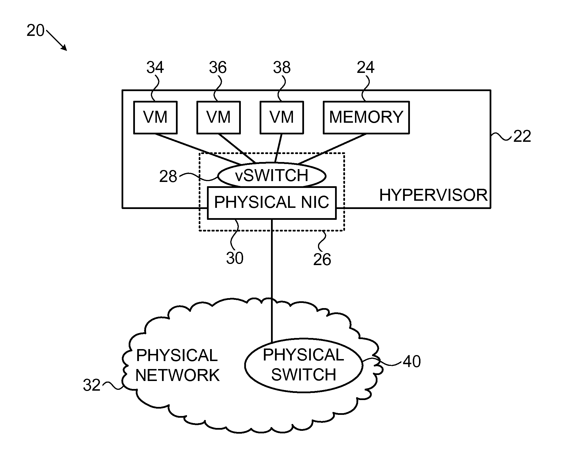
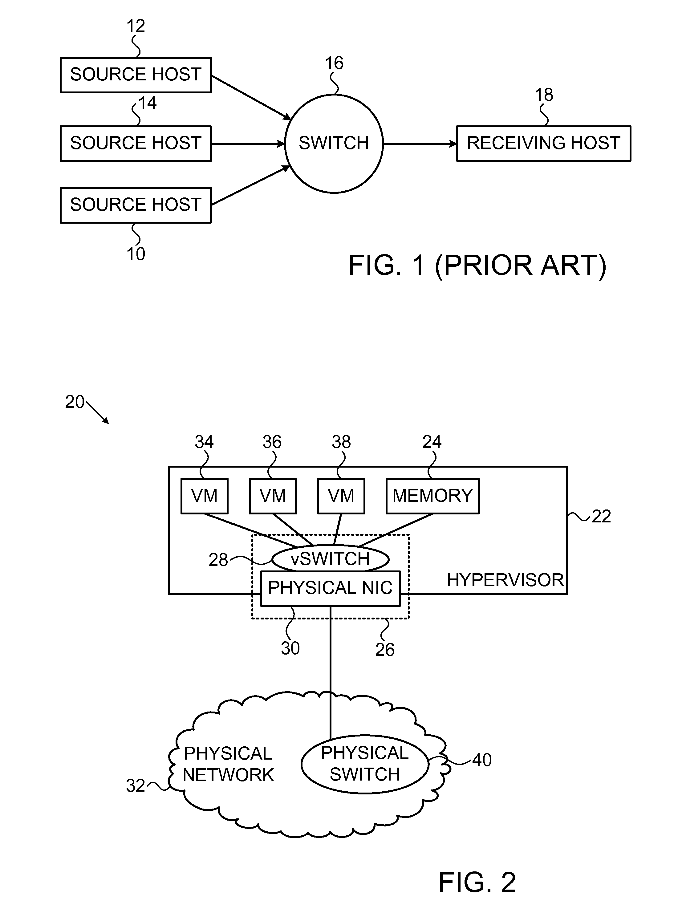
[0068]Reference is now made to FIG. 2, which is a detailed block diagram of a virtualized network environment subject to congestion control, in accordance with an embodiment of the invention. A host processor 20 comprises a hypervisor 22 and is configured to access suitable memory 24.

[0069]The host processor 20 includes network interface hardware 26, a network interface card 30 (NIC) configured to transmit and receive data packets over a physical data network 32. The network interface hardware 26 may comprise a virtual switch 28 as shown in FIG. 2. Alternatively, the virtual switch 28 may be an element of the hypervisor 22 and in some embodiments may be realized as multiple virtual switches. The hypervisor 22 may support any number of virtual machines (VMs), here represented by three virtual machines 34, 36, 38. The hypervisor 22 is linked to a physical switch 40 interfacing the data network 32. Upon reception from the network of packets that have been marked to indicate congestion ...

second embodiment

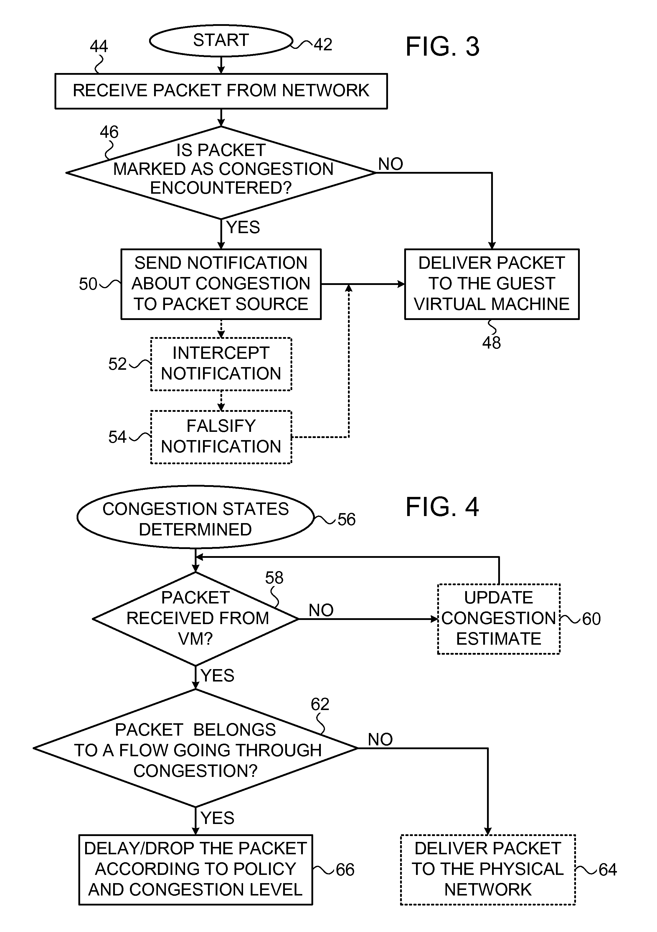
[0097]Referring again to FIG. 3 and FIG. 4, performance of step 50 and final step 66 indicate non-compliance with the congestion-control mechanism. These steps may include a signal to a billing system, charging users based upon the amount of congestion encountered. This approach can create a financial incentive to comply with congestion control policies.

third embodiment

[0098]Reverting to FIG. 3, step 50 may provide a graphical indication of VMs that cause congestion, and can be used as an input for VM migration decision processes. For example, if a VM produces a large amount of congestion on a current machine, e.g., a predetermined percentage of the network bandwidth, recognition of server overload may indicate migrating the VMs that cause the most congestion. This approach can help to reduce the number of congested links in the network. One congestion metric for purpose of step 50 is a ranking in each hypervisor according to congestion control limitations of its respective flows. A VM having more than a given percentage of its flows subject to congestion control restrictions becomes a candidate for migration.


PUM


Abstract

In a data network congestion control in a virtualized environment is enforced in packet flows to and from virtual machines in a host. A hypervisor and network interface hardware in the host are trusted components. Enforcement comprises estimating congestion states in the data network attributable to respective packet flows, recognizing a new packet that belongs to one of the data packet flows, and using one or more of the trusted components and to make a determination based on the congestion states that the new packet belongs to a congestion-producing packet flow. A congestion-control policy is applied by one or more of the trusted components to the new packet responsively to the determination.

Description

CROSS-REFERENCE TO RELATED APPLICATIONS[0001]This Application claims the benefit of U.S. Provisional Application No. 61 / 859,247, filed Jul. 28, 2013, which is herein incorporated by reference.BACKGROUND OF THE INVENTION[0002]1. Field of the Invention[0003]This invention relates to communication networks. More particularly, this invention relates and particularly to congestion control in communication network virtualization.[0004]2. Description of the Related Art[0005]The meanings of certain acronyms and abbreviations used herein are given in Table 1.TABLE 1Acronyms and AbbreviationsARPAddress Resolution ProtocolCNMCongestion-notification messageDCTCPDatacenter TCPECNExplicit Congestion NotificationIBInfiniBandIETFInternet Engineering Task ForceIPInternet Protocol; Also Internet Protocol AddressNICNetwork Interface CardNVGRENetwork Virtualization using Generic Routing EncapsulationOSIOpen Systems InterconnectionQCNQuantized Congestion NotificationQPQueue Pair (a transmit queue and a ...

Claims


Application Information

Patent Timeline
IPC IPC(8): H04L12/801H04L12/851H04L12/931
CPCH04L47/127H04L47/2441H04L49/70G06F3/0662G06F3/0664H04L12/4633H04L49/50
Inventor RAINDEL, SHACHARBLOCH, NOAMLISS, LIRANCRUPNICOFF, DIEGOLIPSHTEYN, MARINA
Owner MELLANOX TECHNOLOGIES LTD
Why Eureka
Try Eureka