

Carbon dioxide chemical sequestration from industrial emissions by carbonation
- Summary
- Abstract
- Description
- Claims
- Application Information
AI Technical Summary
Benefits of technology
Problems solved by technology
Method used
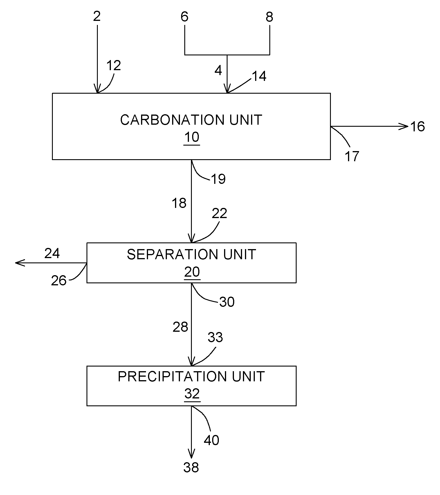
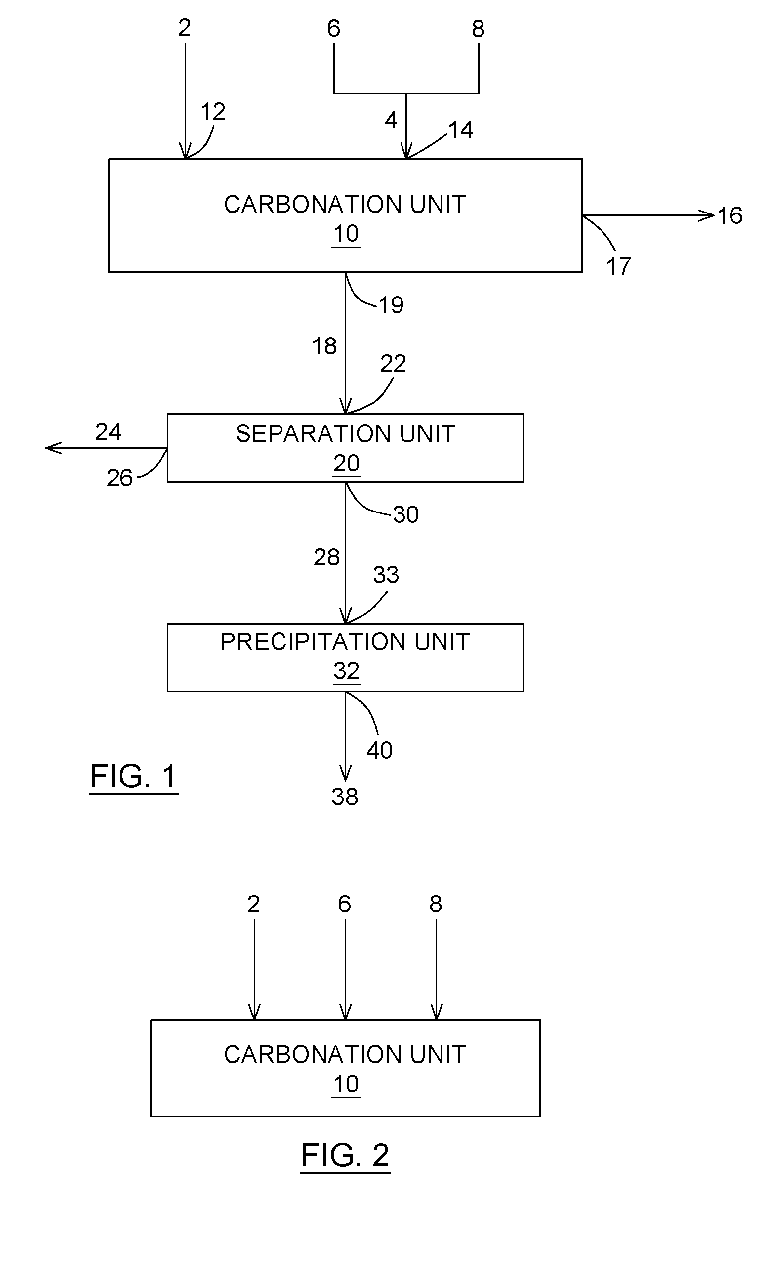
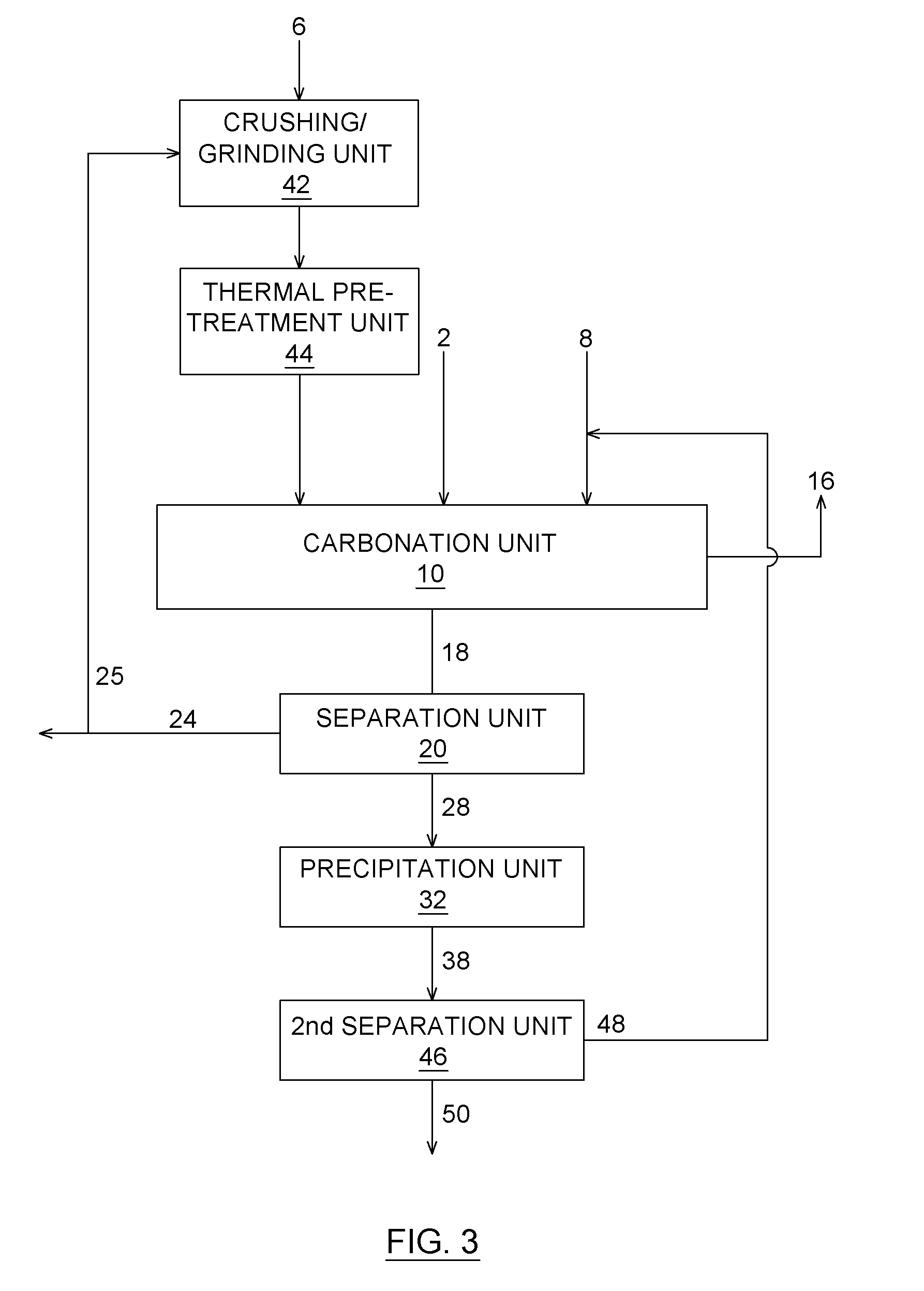
Image

Examples
example 1
Wet Carbonation of Chrysotile Mining Residues
[0142]A first series of experiments were carried out, using chrysotile mining residues composed of lizardite, antigorite, brucite, iron oxides, chromium oxides and a low content of chrysotile, to optimize conditions for the wet carbonation on sample size of around 7 g with grain size inferior to 75 μm and a pulp density of 15% (a mass of 150 g of solid per liter of liquid). The temperature and reaction duration were kept stable at 25° C. and 6 h respectively. The variable parameters are pressure, NaCl and NaHCO3 content and heat treated sample or not. They were optimized on the basis of percentage of CO2 removal and the percentage of solid carbonate formed (dependent variables). The various conditions and results obtained are given in Table 1.
[0143]From this table, it appears that a removal of CO2 up to 87% can be achieved for a pressure of 10.2 atm and heat treated sample. CO2 removal seems independent from NaCI content and slightly depe...
example 2
Wet Carbonation of Serpentinite
[0146]This experiment describes the feasibility of the process for the treatment of a batch of gas containing 18.2% of carbon dioxide during 15 minutes. The gas liquid ratio (GLR) was fixed at 300% which represents a volume of carbon dioxide containing gas of 225 mL and a volume of 75 mL of water. The resulting aqueous slurry had a 15 wt % concentration of solid material. Reaction temperature was set at ambient temperature (18-25° C.). A pressure of 10.5 bars was applied which represented an amount of 0.78 g of CO2 at 20° C. Once the pressure reached, all valves of the reactor were closed and reaction occurred for 15 minutes. The resulting carbon dioxide depleted gas was then sampled through a bag. The carbon dioxide concentration in the carbon dioxide depleted gas was measured by a CO2 analyzer. The resulting aqueous slurry was filtered and samples were taken for analysis.
[0147]Reaction under ambient temperature at 10.5 bars during 15 minutes showed a...
example 3
Optimisation of Thermal Pre-Treatment of Serpentinite Before Wet Carbonation
[0148]Another series of experiments was performed to show that the thermal pre-treatment of the alkaline earth metal containing material favors a good removal of carbon dioxide from the carbon dioxide containing gas.
[0149]A serpentinite based mining residue was used as alkaline earth metal containing material. Firstly, depending on the grain size, the residue was crushed, and then grinded. The best results were obtained with samples with a particle size lower than 45 μm (median size 10 μm). In order to obtain a chemically reactive material, the serpentinite based mining residue has to be further pre-treated to allow dehydroxylation of the serpentinite. By removing water from the various crystalline structures of the minerals, the chemical structure of the sample is altered and thus lowers the bound energies. The heat activation of hydrated silicates is well known to favour chemical activation prior to lixivi...
PUM
| Property | Measurement | Unit |
|---|---|---|
| Temperature | aaaaa | aaaaa |
| Temperature | aaaaa | aaaaa |
| Fraction | aaaaa | aaaaa |
Abstract
Description
Claims
Application Information