Methods and systems for three dimensional optical imaging, sensing, particle localization and manipulation

a three-dimensional optical imaging and sensing technology, applied in image enhancement, image analysis, instruments, etc., can solve the problems of loss of restoration quality in the mtf, affecting the axial range or three-dimensional imaging and sensing, and both classical lenses and axial invariant solutions implemented are by definition ill-suited for axial ranging or three-dimensional imaging and sensing, and the point spread function designed for three-dimensional imaging has therefore been ill-suited for extended depth of field

Active Publication Date: 2015-02-05
UNIV OF COLORADO THE REGENTS OF
View PDF1 Cites 18 Cited by
  • Summary
  • Abstract
  • Description
  • Claims
  • Application Information

AI Technical Summary

Benefits of technology

[0014]Particles are typically smaller than the diffraction limit of the imaging optics. Some embodiments use a point spread function (PSF) with a predefined three dimensional shape to obtain high Fisher information in 3D. The PSF may be generated via a phase mask, an amplitude mask, a hologram, or a diffractive optical element, merely by way of example. Small particles may be imaged using the 3D PSF. The images may be used to find the precise location of the particles using an estimation algorithm such as maximum likelihood estimation (MLE), expectation maximization, or Bayesian methods, for example. Calibration measurements can be used to improve the theoretical model of the optical system. Fiduciary particles can also be used to compensate for drift and other type of movement of the sample relative to the detector.
[0020]Some embodiments provide shaping the three dimensional pattern of light waves for an enhanced signal to be used for direct measurements or later reconstruction using digital algorithms in digital imaging, sensing or manipulation of objects located with a volume. Still yet, some embodiments can use spinning point spread functions which are an improvement on methods which demonstrated axial ranging and three dimensional imaging—including simultaneous combinations thereof to provide a 3D image in-focus over a wide depth range.

Problems solved by technology

Such systems have required a trade-off between axial invariance and suppression of the spatial frequency content and hence loss of restoration quality in the MTF.
Both classical lenses and the axial invariant solutions implemented are by definition ill-suited for axial ranging or three dimensional imaging and sensing.
Point spread functions designed for three dimensional imaging have therefore been ill-suited for extended depth of field.
However, the resolution of these techniques are not as fine as desired.
Nevertheless, the newly discovered frontiers of optical resolution and functionality—such as quantitative tracking and distance measurement—have not been fully realized yet.

Method used


Image

  • Methods and systems for three dimensional optical imaging, sensing, particle localization and manipulation
  • Methods and systems for three dimensional optical imaging, sensing, particle localization and manipulation
  • Methods and systems for three dimensional optical imaging, sensing, particle localization and manipulation

Examples


Embodiment Construction

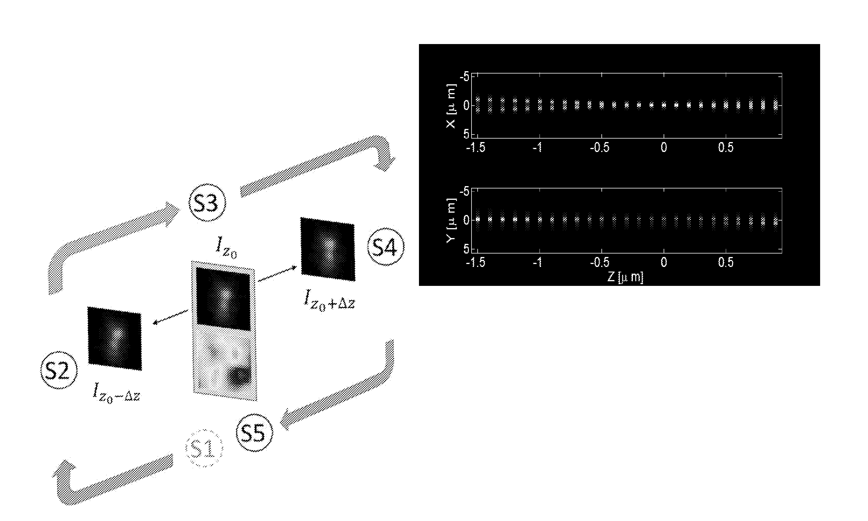
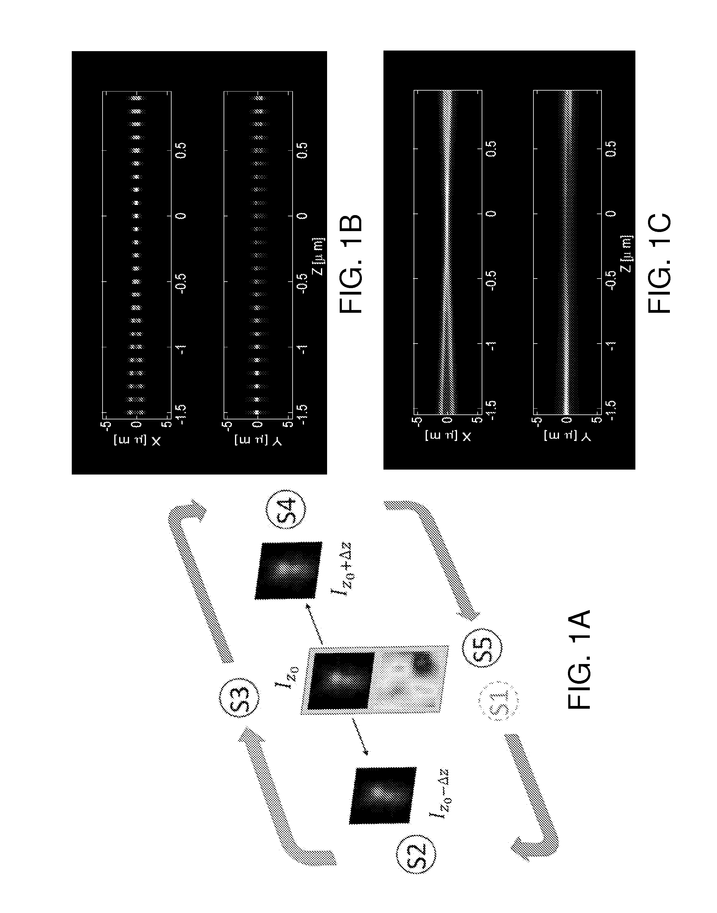
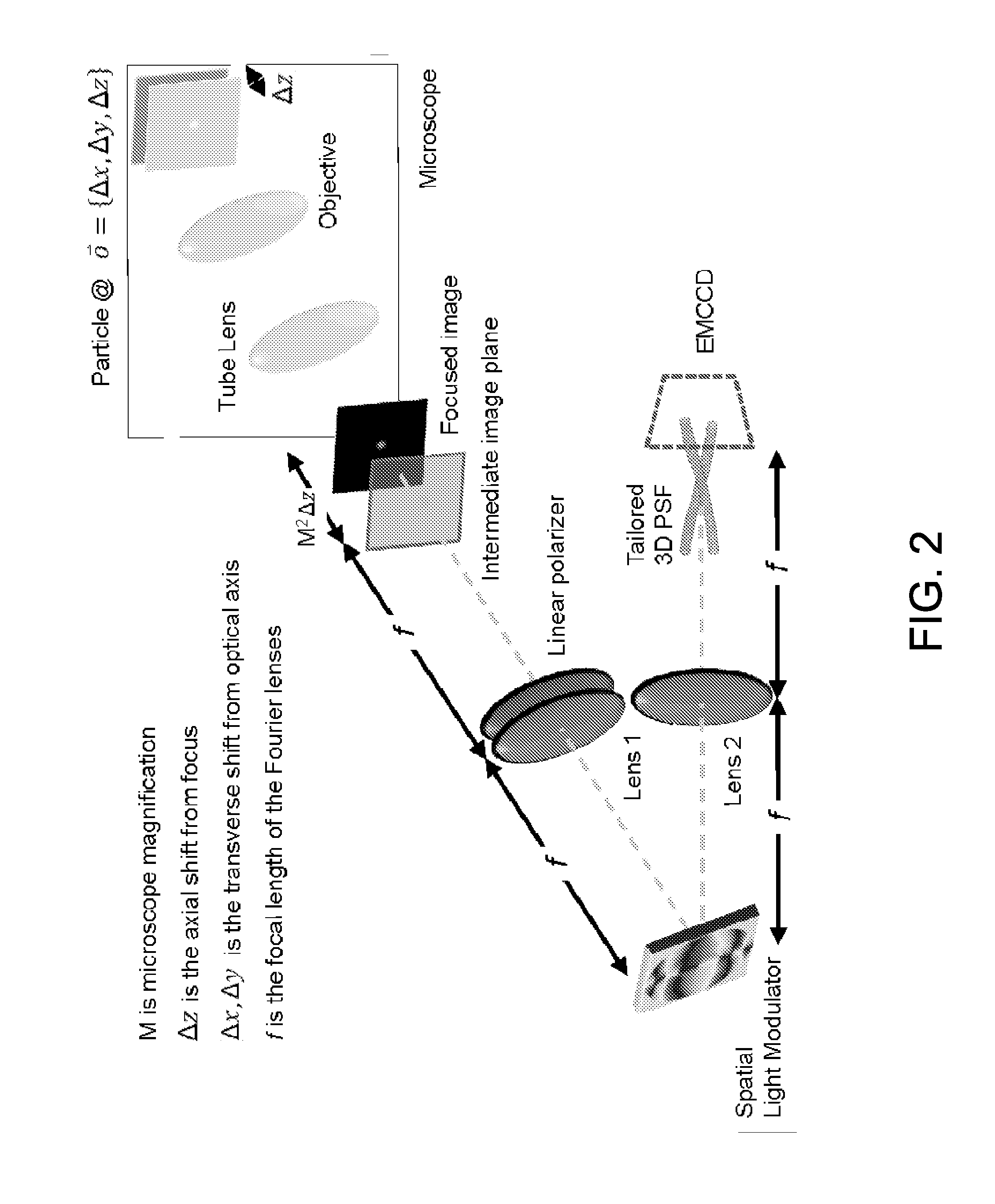
[0048]Various embodiments of the present invention generally relate to systems and methods with optimal 3D localization procedures in photo-activation localization microscopy. More specifically, some embodiments relate systems and methods for precise object or particle position estimation in 3D with an increased resolution for a given number of photons detected and reduced data acquisition time for a given target resolution. For example, in some embodiments, the stochastic emission of light from molecule ensembles may be imaged as a collection of Point Spread Function (PSF), which may be used for individual estimation of the position of each particle in 3D. A wide-field image may be rendered as the composite of all the estimations from time-multiplexed emission measurements. As an additional example, in some embodiments, the light reflected / emitted / transmitted from an object may be imaged as the convolution of the Point Spread Function (PSF) and the object, which may be used for est...


PUM


Abstract

Embodiments include methods, systems, and / or devices that may be used to image, obtain three-dimensional information from a scene, and / or locate multiple small particles and / or objects in three dimensions. A point spread function (PSF) with a predefined three dimensional shape may be implemented to obtain high Fisher information in 3D. The PSF may be generated via a phase mask, an amplitude mask, a hologram, or a diffractive optical element. The small particles may be imaged using the 3D PSF. The images may be used to find the precise location of the object using an estimation algorithm such as maximum likelihood estimation (MLE), expectation maximization, or Bayesian methods, for example. Calibration measurements can be used to improve the theoretical model of the optical system. Fiduciary particles / targets can also be used to compensate for drift and other type of movement of the sample relative to the detector.

Description

GOVERNMENT LICENSE RIGHTS[0001]This invention was made with government support under grant numbers 0082885 and 0801680 awarded by the National Science Foundation. The government has certain rights in the invention.TECHNICAL FIELD[0002]Various embodiments of the present invention generally relate to systems and methods for 3D imaging and sensing as well as 3D localization with optimal procedures, some of which are applicable in photo-activation localization microscopy and stochastic optical reconstruction microscopy. More specifically, some embodiments relate to systems and methods for precise particle position estimation in 3D that provide an increased resolution for a given number of photons detected and reduced data acquisition time for a given target resolution. Some embodiments also relate to the retrieval of 3D information from images at any scale, macroscopic or microscopic.BACKGROUND[0003]The use of digital devices to collect and store irradiance patterns representative of th...

Claims


Application Information

Patent Timeline
Patent Type & Authority Applications(United States)
IPC IPC(8): H04N13/02G06T7/00
CPCH04N13/0203G06T2207/10064G06T2207/10056G06T7/0048G06T7/77H04N13/204
Inventor PIESTUN, RAFAELQUIRIN, SEAN ALBERT
Owner UNIV OF COLORADO THE REGENTS OF
Why Eureka
Try Eureka