Over-current and over-voltage protection circuit and method for an electronic cigarette

a protection circuit and electronic cigarette technology, applied in the field of electronic cigarettes, can solve the problems of adverse effects on the longevity and performance of the battery, adverse effects on the battery in the battery pole, and serious burns and explosions

Inactive Publication Date: 2015-02-05
HUIZHOU KIMREE TECH
View PDF2 Cites 60 Cited by
  • Summary
  • Abstract
  • Description
  • Claims
  • Application Information

AI Technical Summary

Benefits of technology

[0050]When implementing the over-current and over-voltage protection circuit and method for the electronic cigarette of the present application, the following advantageous effects can be achieved: the charging detection switch unit can not only detect the actual charging current in the charging status real-timely, and send the actual charging current to the control unit, but also turn off the connection between the battery and the external circuit under the control of the control unit when the control unit determines that the actual charging current is in the over-current status, so that the over-current protection can be achieved in the charging status, and the control unit can detect the input voltage of the interface directly, and turn off the charging detection switch unit when the input voltage is in the over-voltage status. The present application further provides the discharging detection switch unit, and the discharging detection switch unit can achieve the over-current protection in the discharging process. Therefore, the over-current and over-voltage protection circuit and method of the present application eliminate the security risk of the battery pole not having a charging management circuit in the non-normal charging status. A current sampling process of the present application doesn't need an external sampling resistor, and a characteristic that a conducting internal resistance of the MOSFET is small is directly utilized; and the dropout voltage between the drain and the source of the MOSFET is sent to the microprocessor of the control unit, and the microprocessor obtains the current flowing through the over-current and over-voltage protection circuit basing on the dropout voltage between the drain and the source of the MOSFET and the conducting internal resistance of the MOSFET; and the microprocessor determines whether the electrical connection between the battery, and the charger or the atomizer should be driven to be turned off according to the comparing result between the current flowing through the over-current and over-voltage protection circuit and the corresponding preset current threshold value. It need be noticed that a current direction in the charging status is opposite to the current direction in a discharging status, so that the microprocessor can only detect a plus dropout voltage of the charging detection switch unit in the charging process status, and can only detect a plus dropout voltage of the discharging detection switch unit in the discharging process status. Thus, the automatic determination of the charging and discharging processes is achieved, and the whole circuit structure is simpler.
can be achieved: the charging detection switch unit can not only detect the actual charging current in the charging status real-timely, and send the actual charging current to the control unit, but also turn off the connection between the battery and the external circuit under the control of the control unit when the control unit determines that the actual charging current is in the over-current status, so that the over-current protection can be achieved in the charging status, and the control unit can detect the input voltage of the interface directly, and turn off the charging detection switch unit when the input voltage is in the over-voltage status. The present application further provides the discharging detection switch unit, and the discharging detection switch unit can achieve the over-current protection in the discharging process. Therefore, the over-current and over-voltage protection circuit and method of the present application eliminate the security risk of the battery pole not having a charging management circuit in the non-normal charging status. A current sampling process of the present application doesn't need an external sampling resistor, and a characteristic that a conducting internal resistance of the MOSFET is small is directly utilized; and the dropout voltage between the drain and the source of the MOSFET is sent to the microprocessor of the control unit, and the microprocessor obtains the current flowing through the over-current and over-voltage protection circuit basing on the dropout voltage between the drain and the source of the MOSFET and the conducting internal resistance of the MOSFET; and the microprocessor determines whether the electrical connection between the battery, and the charger or the atomizer should be driven to be turned off according to the comparing result between the current flowing through the over-current and over-voltage protection circuit and the corresponding preset current threshold value. It need be noticed that a current direction in the charging status is opposite to the current direction in a discharging status, so that the microprocessor can only detect a plus dropout voltage of the charging detection switch unit in the charging process status, and can only detect a plus dropout voltage of the discharging detection switch unit in the discharging process status. Thus, the automatic determination of the charging and discharging processes is achieved, and the whole circuit structure is simpler.

Problems solved by technology

Defect 1: external chargers in the prior art have different charging current magnitudes; and when a low-capacity battery is charged by a high current, the longevity and performance of the battery will be affected adversely.
Defect 2: if the external charger lose efficacy, or don't have a current-limiting function or voltage-limiting function, the battery in the battery pole will be affected adversely, and will leak, burn and even explode seriously.
Defect 3: if a user uses a wrong charger, and uses the charger not having a charging management function to charge a battery pole, a burning and an exploded accident of the battery will be caused.
Therefore, there is a big security risk of the battery pole of the electronic cigarette not having a charging management function in a non-normal charging status, and the battery pole of the electronic cigarette needs to be improved.

Method used


Image

  • Over-current and over-voltage protection circuit and method for an electronic cigarette
  • Over-current and over-voltage protection circuit and method for an electronic cigarette
  • Over-current and over-voltage protection circuit and method for an electronic cigarette

Examples


Embodiment Construction

[0055]To make the technical feature, objective and effect of the present application be understood more clearly, now the specific implementation of the present application is described in detail with reference to the accompanying drawings and embodiments.

[0056]To overcome the defect that there is a security risk of a battery pole not having a charging management circuit in a non-normal charging status in the prior art, the present provides an over-current over-voltage protection circuit for an electronic cigarette, aiming at a battery pole not having a charging management circuit. This over-current and over-voltage protection circuit can avoid that the charging voltage and the charging current are exaggerated, when the battery pole is in a charging status. Moreover, the over-current and over-voltage protection circuit can prevent the discharging current of the battery pole from exaggerated, when the battery pole is in a discharging status.

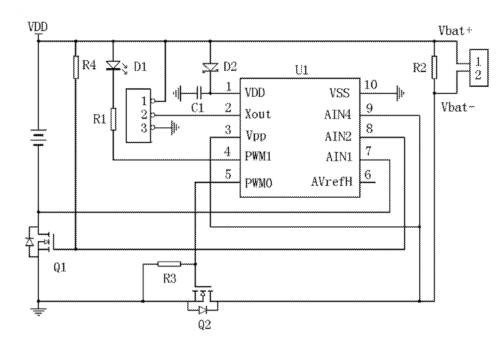
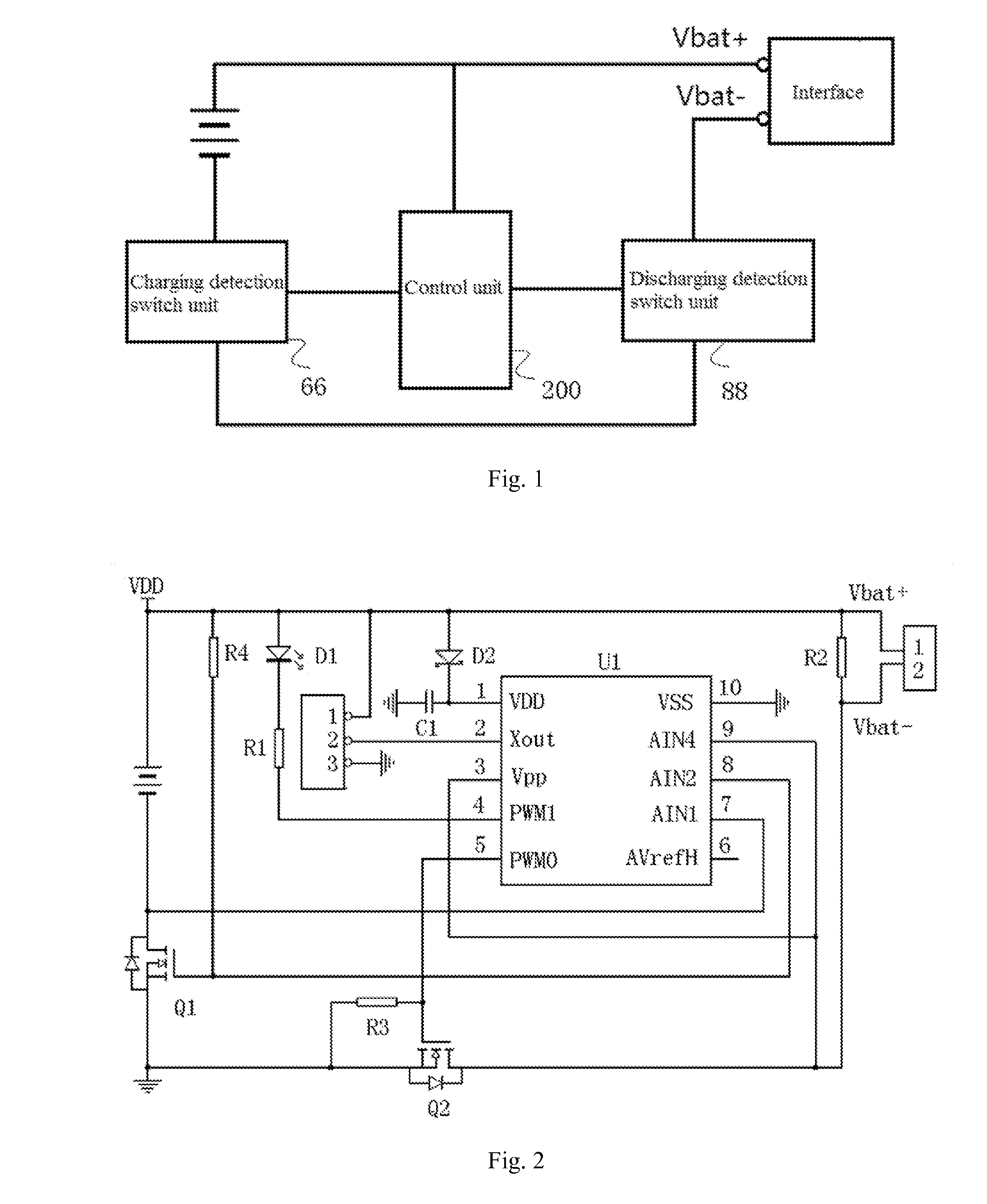
[0057]As shown in FIG. 1, FIG. 1 is a struct...


PUM


Abstract

An over-current and over-voltage protection circuit for an electronic cigarette, comprising a battery and an interface, a control unit and a charging detection switch unit; the control unit is configured for calculating an actual charging current according to the first working voltage and determining whether the actual charging current exceeds a preset charging current threshold value, and sending a first charging controlling signal to the charging detection switch unit; the control unit is further configured for real-timely detecting an input voltage of the interface, determining whether the input voltage of the interface is in over-voltage status, and controlling a turned-on or turned-off operation of the charging detection switch unit. The over-current over-voltage protection circuit and method eliminate the security risk of the battery pole not having a charging management circuit in the non-normal charging status.

Description

CROSS-REFERENCE TO RELATED APPLICATIONS[0001]This non-provisional application claims priority under 35 U.S.C. §119(a) on Patent Application No. 201310330134.5, filed in P.R. China on Jul. 31, 2013, the entire contents of which are hereby incorporated by reference.FIELD OF THE INVENTION[0002]The present application relates to the field of electronic cigarettes, and more particularly relates to an over-current and over-voltage protection circuit and method adapted for a charging process and a discharging process of the electronic cigarette.BACKGROUND OF THE INVENTION[0003]At present, chargeable battery poles of electronic cigarettes not having a charging management circuit in the prior art (e.g., electronic cigarettes controlled by some microcontrollers) don't have an over-voltage charging protection function and an over-current charging protection function in a charging process. These chargeable battery poles of electronic cigarettes entirely rely on a battery charging management chi...

Claims


Application Information

Patent Timeline
Patent Type & Authority Applications(United States)
IPC IPC(8): H02J7/00A24F40/53A24F40/90
CPCH02J7/0029H02J7/00304H02J7/00302H02J7/00308A24F40/53A24F40/90Y02T10/70
Inventor XIANG, ZHIYONG
Owner HUIZHOU KIMREE TECH
Why Eureka
Try Eureka