Multi charged particle beam writing method, and multi charged particle beam writing apparatus
a writing apparatus and charged particle technology, applied in discharge tube/lamp details, instruments, heat measurement, etc., can solve the problems of large size of shaping aperture plate, long writing time, and limit to this method
- Summary
- Abstract
- Description
- Claims
- Application Information
AI Technical Summary
Benefits of technology
Problems solved by technology
Method used
Image
Examples
first embodiment
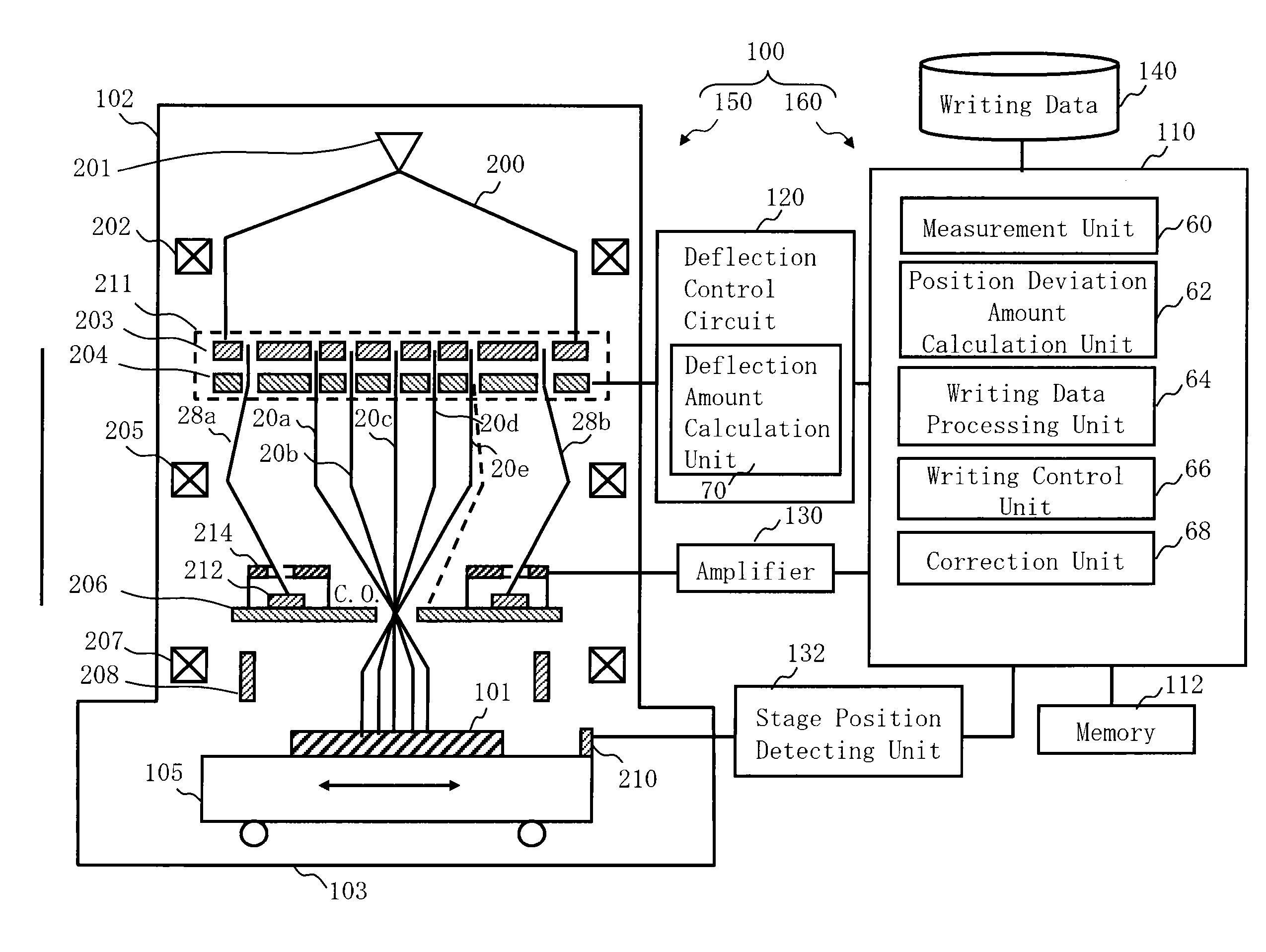
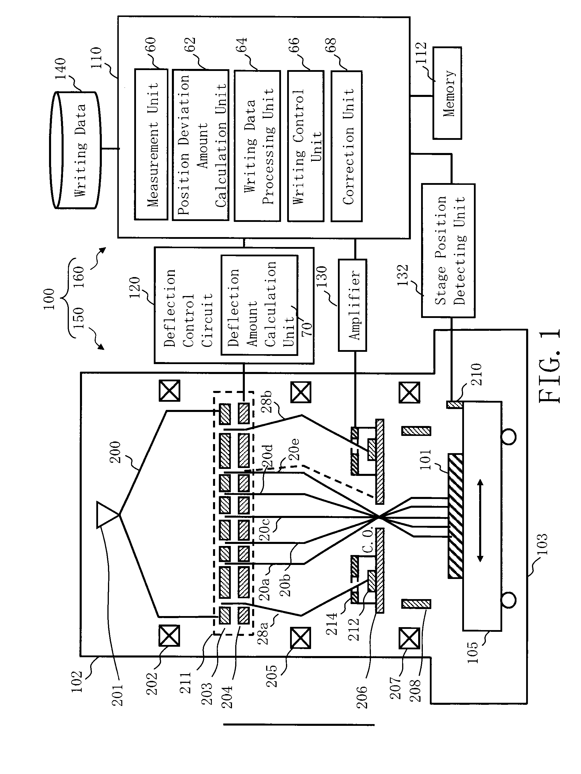
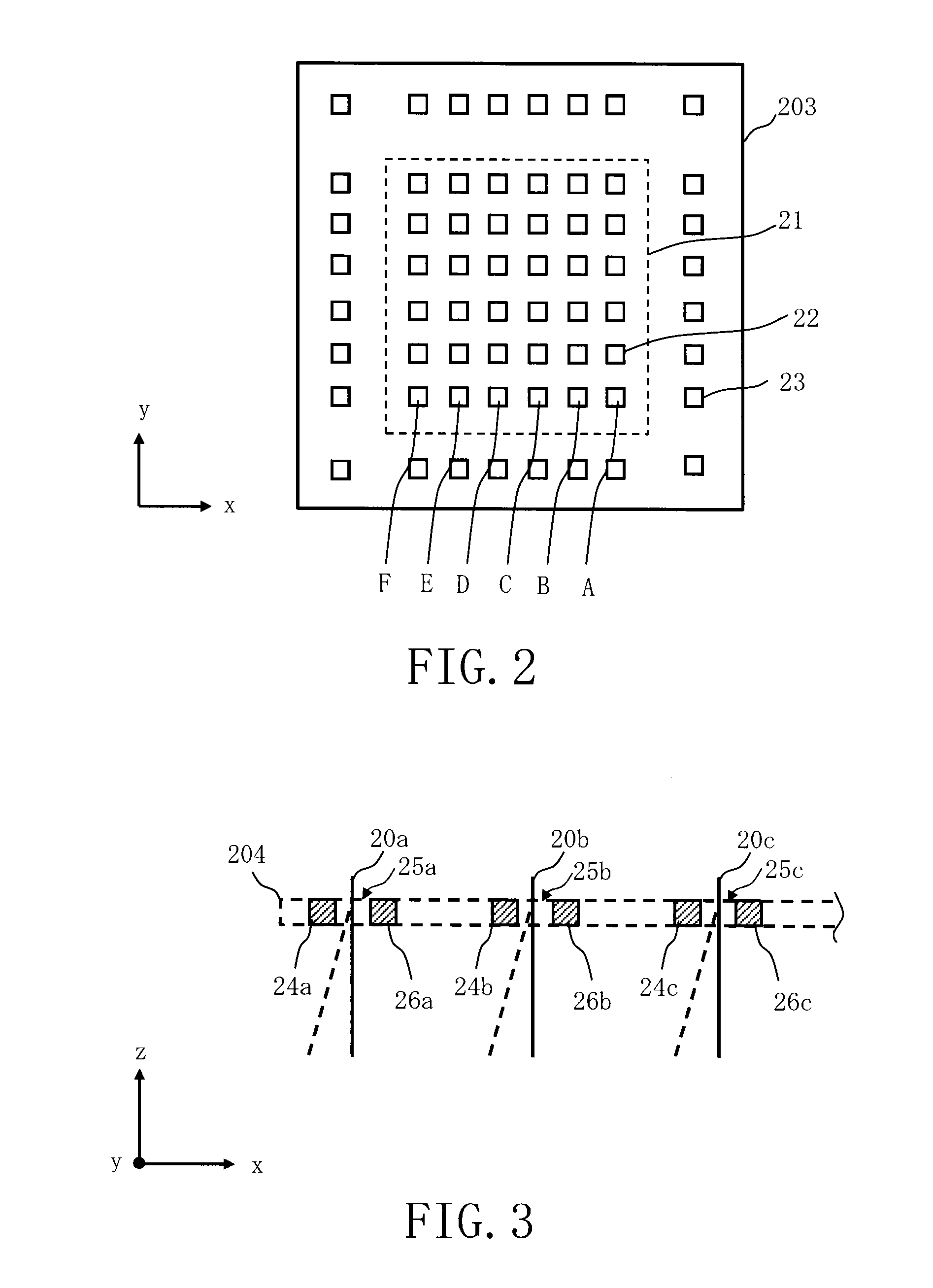
[0026]FIG. 1 is a schematic diagram showing a configuration of a writing apparatus according to the first embodiment. In FIG. 1, a writing (or “drawing”) apparatus 100 includes a writing unit 150 and a control unit 160. The writing apparatus 100 is an example of a multi charged particle beam writing apparatus. The writing unit 150 includes an electron optical column 102 and a writing chamber 103. In the electron optical column 102, there are arranged an electron gun assembly 201, an illumination lens 202, a blanking aperture array (BAA) member 211, a converging lens 205, a limiting aperture member 206, an objective lens 207, and a deflector 208. The BAA member 211 is composed of laminated shaping aperture member 203 and blanking plate 204, where the shaping aperture member 203 is the upper side. On the limiting aperture member 206, there are arranged a plurality of mark members 212 and a plurality of detectors 214 each arranged for each mark member 212. In the writing chamber 103, t...
second embodiment
[0066]In the first embodiment, the case in which the position of the multiple beams 28 for measurement is measured near the height position of the crossover surface has been described, but however, it is not limited thereto. In the second embodiment, the case in which the position of the multiple beams 28 for measurement is measured at a position in the middle to the crossover position will be described.
[0067]FIG. 12 is a schematic diagram showing the structure of a writing apparatus according to the second embodiment. FIG. 12 is the same as FIG. 1 except that a plurality of mark members 212 are arranged between the blanking plate 204 and the limiting aperture member 206, and a measurement plate 215 (support member) which supports a plurality of mark members 212 is arranged. The contents of the second embodiment are the same as those of the first embodiment except what is particularly described below. One measurement plate 215 in which an opening is formed at the central part may su...
PUM
 Abstract
Description
Claims
Application Information
 - R&D
- Intellectual Property
- Life Sciences
- Materials
- Tech Scout
- Unparalleled Data Quality
- Higher Quality Content
- 60% Fewer Hallucinations
Browse by: Latest US Patents, China's latest patents, Technical Efficacy Thesaurus, Application Domain, Technology Topic, Popular Technical Reports.
© 2025 PatSnap. All rights reserved.Legal|Privacy policy|Modern Slavery Act Transparency Statement|Sitemap|About US| Contact US: help@patsnap.com


