
Device for detecting banknote thickness

Active Publication Date: 2015-02-12
KISAN ELECTRONICS
View PDF6 Cites 7 Cited by
  • Summary
  • Abstract
  • Description
  • Claims
  • Application Information

AI Technical Summary

Benefits of technology

The patent describes a device that can detect the thickness of banknotes using an electrostatic capacity property. This device is cost-effective, easy-to-use, and can detect a variety of features on banknotes, including holograms, security threads, metal fibers, and even moisture. It can even distinguish between banks that are thick due to stains, moisture, or crumple. The device improves accuracy in identifying banknote thickness.

Problems solved by technology

Thus, a ultrasonic sensor scheme or a thickness detection roller scheme conventionally used for detecting a thickness of a banknote may erroneously determine a sheet of old banknote as two or more sheets of new banknote, or conversely, erroneously determine two or more sheets of new banknote as a sheet of old banknote and incurs high manufacturing costs.

Method used


Image

  • Device for detecting banknote thickness
  • Device for detecting banknote thickness
  • Device for detecting banknote thickness

Examples


Embodiment Construction

[0026]Hereinafter, a device for detecting a banknote thickness and a method hereof according to exemplary embodiments of the present invention will be described with reference to the accompanying drawings.

[0027]In the drawings, thicknesses of lines, dimensions of elements, and the like, may be exaggerated for clarity and convenience. Also, terms described hereinafter may be defined in consideration of functions in exemplary embodiments of the present invention and may be changed according to an intention or a custom of a user or an operator. Thus, definitions of terms should be defined on the basis of content throughout the specification.

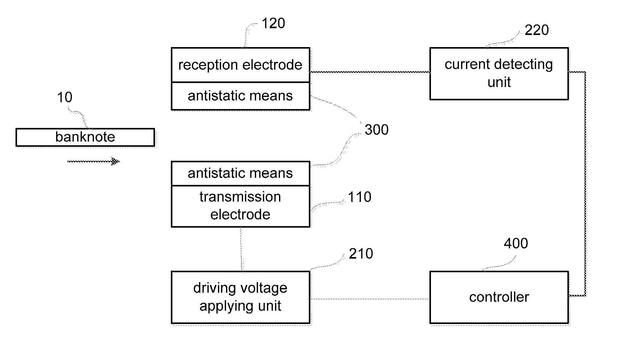
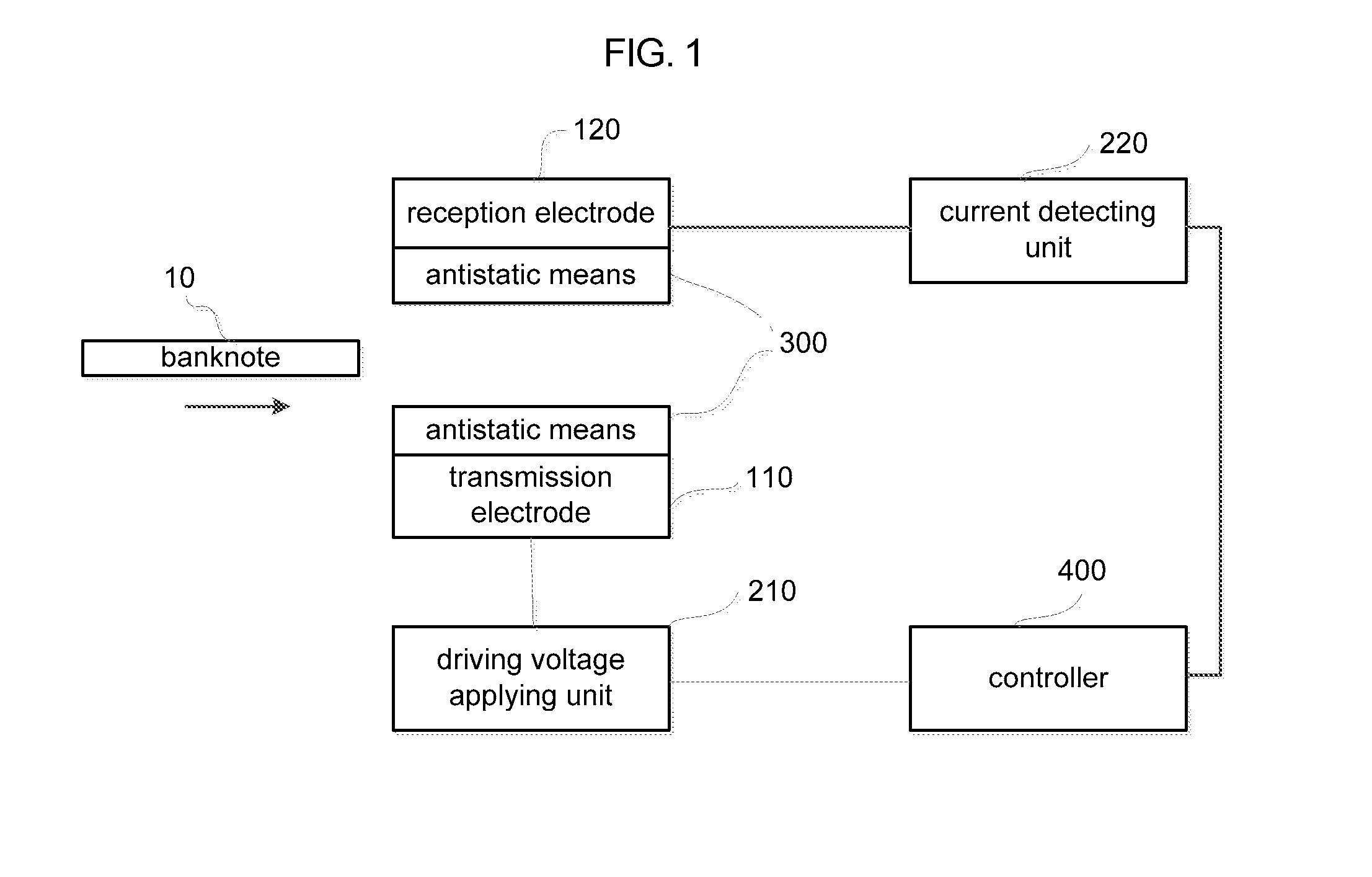
[0028]FIG. 1 is a view illustrating a schematic configuration of a device for detecting a banknote thickness according to an exemplary embodiment of the present invention.

[0029]As illustrated in FIG. 1, the device for detecting a banknote thickness according to the exemplary embodiment of the present invention includes a transmission electrode 110, ...


PUM

PropertyMeasurementUnit
Electrical resistivityaaaaaaaaaa
Thicknessaaaaaaaaaa

Abstract

A device for detecting a banknote thickness includes a transmission electrode and a reception electrode facing one another at a predetermined interval and forming an electric field when a driving voltage is applied thereto; a driving voltage applying unit configured to apply a driving voltage having a pre-determined frequency and form an electric field between the transmission electrode and the reception electrode; a current detecting unit configured to detect a current when a banknote is between the transmission electrode and the reception electrode; an antistatic device configured to remove static electricity from the banknote; and a controller configured to detect at least one of a changed current (e.g., when the banknote is present) and a corresponding voltage waveform, and to detect one or more of a state, a thickness and a type of the banknote based on the detected current change or voltage waveform.

Description

CROSS-REFERENCE TO RELATED APPLICATION[0001]The present application claims the benefits of priority of Korean Patent Application No. 10-2013-0095666 filed with the Korean Intellectual Property Office on Aug. 12, 2013. The content of this application is incorporated herein by reference in its entirety.BACKGROUND OF THE INVENTION[0002]1. Field of the Invention[0003]The present invention relates to a device for detecting a banknote thickness, and more particularly, to a device for detecting a banknote thickness capable of detecting one or more of a thickness of a banknote, a state of a banknote, whether a foreign object is on a banknote, or a type (e.g. denomination or national currency) of a banknote, using an electrostatic capacity property.[0004]2. Description of the Prior Art[0005]In general, a bill validator is installed in a bill counting machine, a vending machine, an automatic teller machine (ATM), or the like, to determine whether an input banknote is proper. For example, the ...

Claims


Application Information

Patent Timeline
IPC IPC(8): G01B7/06
CPCG01B7/087G07D7/026B65H1/00B65H16/00B65H45/00
Inventor JANG, SANG HWANKIM, SUNG AM
Owner KISAN ELECTRONICS
Learn More