Method and optical device for super-resolution localization of a particle

a particle and super-resolution technology, applied in the field of super-resolution microscopy methods and optical devices, can solve the problems of deteriorating algorithms, unable to make rapid adjustments, and both cylindrical-lens and biplane techniques

Active Publication Date: 2015-02-12
IMAGINE OPTIC
View PDF3 Cites 8 Cited by
  • Summary
  • Abstract
  • Description
  • Claims
  • Application Information

AI Technical Summary

Benefits of technology

[0015]introducing, via said wavefront-modulating device, a deformation of the wavefront emitted by said emitting particle, allowing a bijective relationship to be formed between the shape of the image of said emitting particle in the detection plane and the axial position of said emitting parti...

Problems solved by technology

However, a limitation that is common to both the cylindrical-lens and biplane techniques is related to residual optical aberrations that deform the PSF and deteriorate the algorithms for laterally and axially localizing the emitting particle.
Moreover, the depth (range) over which it is possible to determine the axial position of the molecule is limited (to about 1-2 μm) and is entirely fixed by the opto-mechanical elements of the apparatus, meaning that it is impossible to make rapid adjustments.
Thi...

Method used


Image

  • Method and optical device for super-resolution localization of a particle
  • Method and optical device for super-resolution localization of a particle
  • Method and optical device for super-resolution localization of a particle

Examples


Embodiment Construction

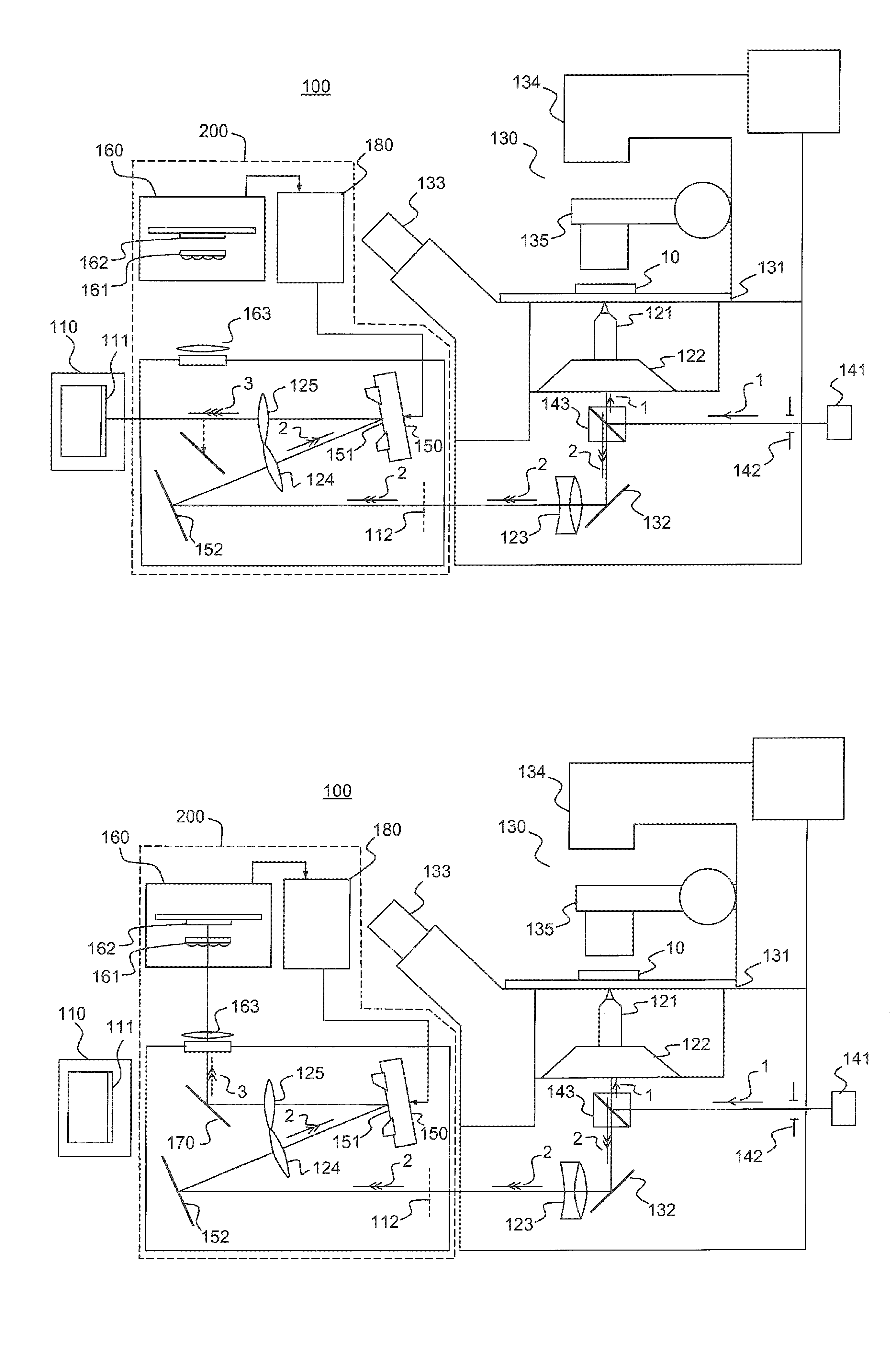
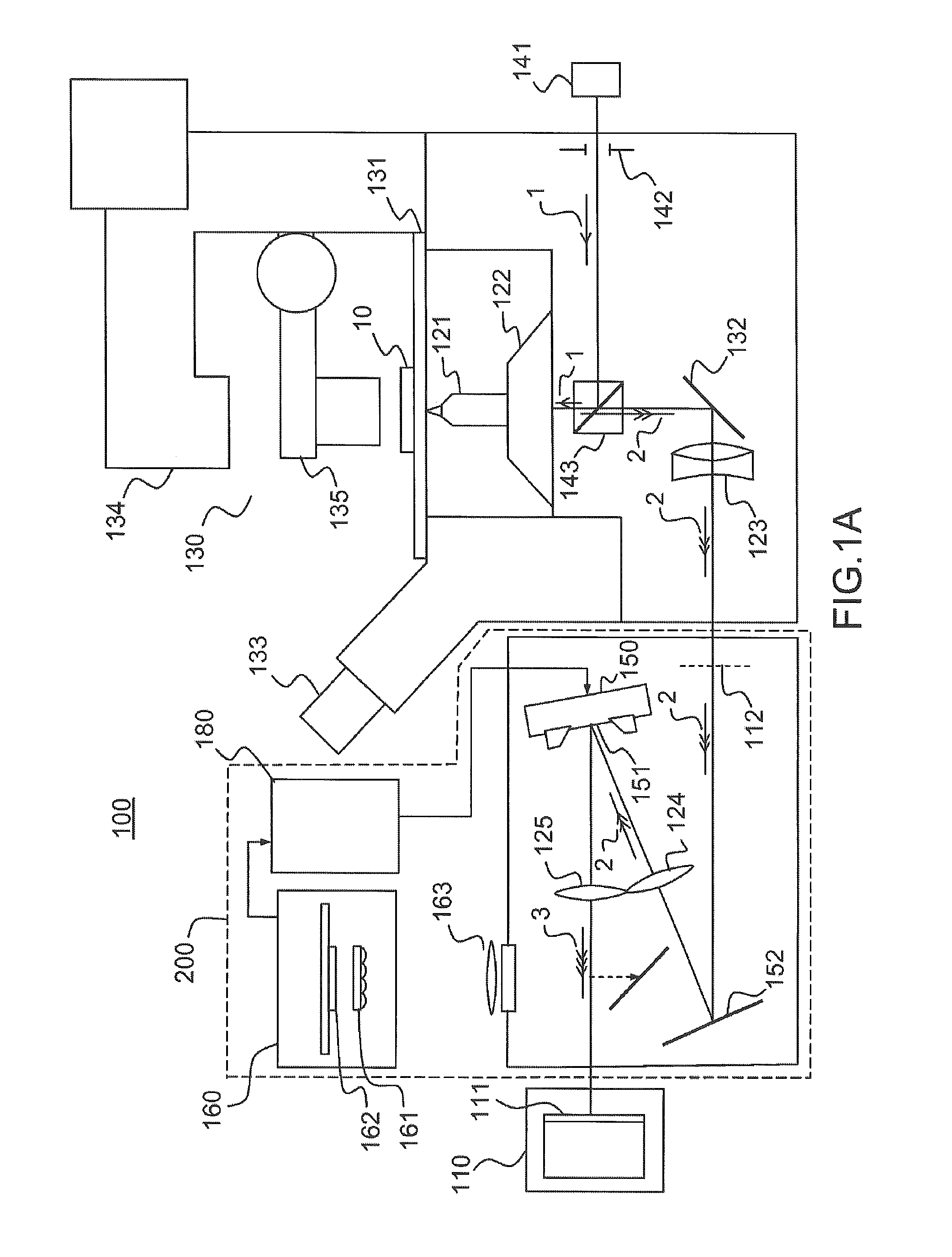
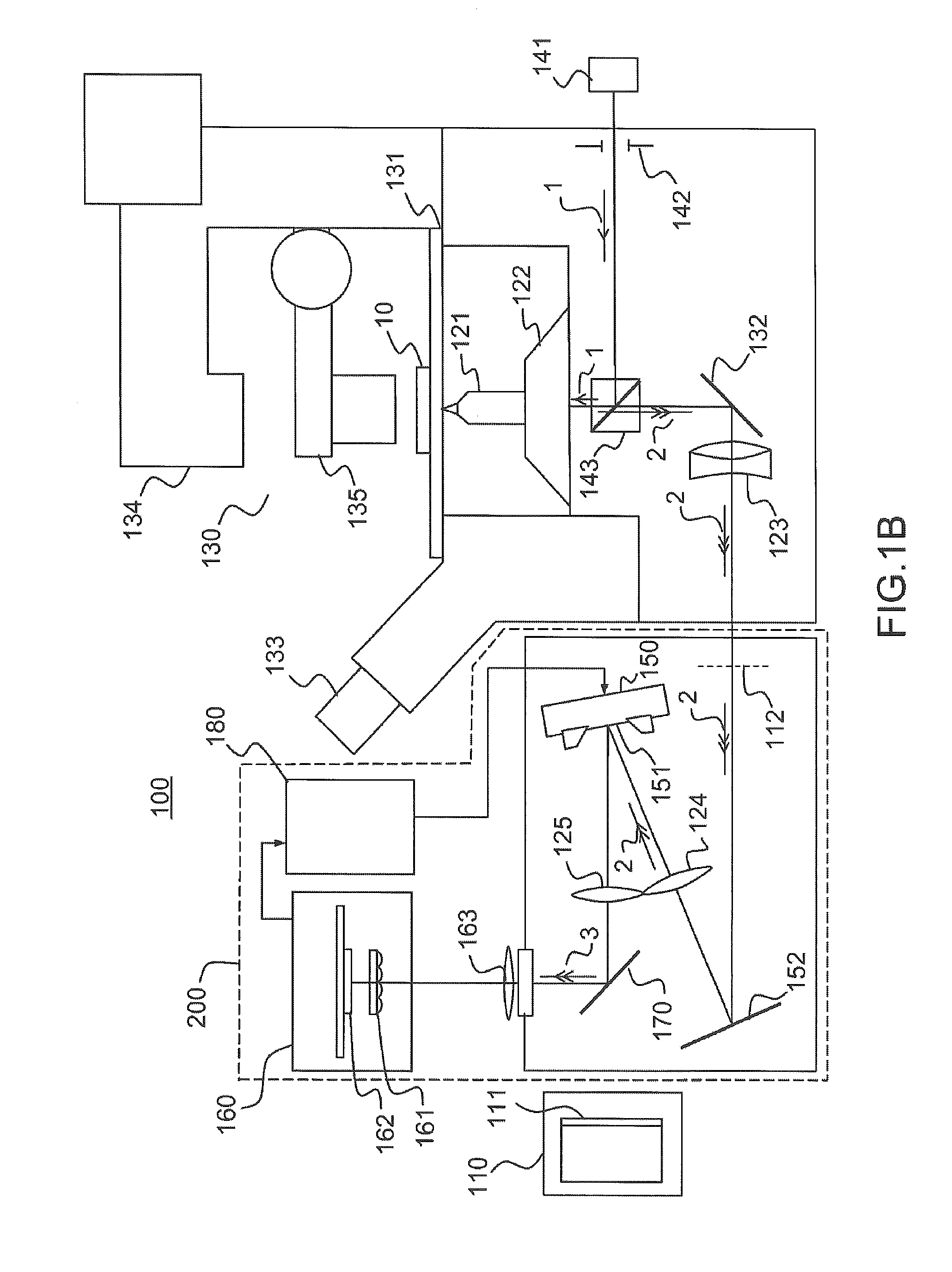
[0048]FIGS. 1A and 1B illustrate a device 100 for three-dimensional localization of one or more emitting particles according to one example of the invention.

[0049]The expression “emitting particle” is understood in the present description to mean any particle capable of emitting a light signal, either spontaneously or by activation, for example by way of a light source (photoactivation). The particles are, for example, reactive units or macromolecular complexes formed by proteins or assemblies of proteins, tagged, using known techniques, with a probe capable of emitting a light signal, for example a fluorescent probe. Average sizes typically range from a few nanometers for small complexes to about 100 nanometers for the largest structures. Most molecular complexes are between 10 and 30 nm in size. In any case, it is desired to localize emitting particles of smaller size than the diffraction limit of the optical system used to form an image thereof. The particles that it is desired t...


PUM


Abstract

A super-resolution microscopy method includes forming an image of an emitting particle in a detection plane of a detector by a microscopy imaging system and correcting, by a wavefront-modulating device, at least some of the optical defects present between the emitting particle and the detection plane. The method further includes introducing, via the wavefront-modulating device, a deformation of the wavefront emitted by the emitting particle, of variable amplitude, allowing a bijective relationship to be formed between the shape of the image of the emitting particle in the detection plane and the axial position of the emitting particle relative to an object plane that is optically conjugated with the detection plane by the microscopy imaging system. The method further includes controlling the amplitude of the deformation of the wavefront by controlling the wavefront-modulating device, as a function of the given range of values of the axial position of the particle.

Description

CROSS REFERENCE TO RELATED APPLICATIONS[0001]This is a national stage application based on PCT / EP2012 / 063511, filed on Jul. 10, 2012, which claims priority to French Patent Application No. 1156647, filed on Jul. 21, 2011. This application claims priority to these prior applications and incorporates their disclosures by reference in their entireties.BACKGROUND[0002]One or more embodiments of the present invention relates to a super-resolution microscopy method and optical device, i.e. with a resolution below the diffraction limit, for three-dimensional localization of one or more particles.[0003]Mankind's understanding of the dynamic architecture of cells is in the process of being completely transformed by technological developments allowing individual molecules to be detected optically in living systems. By virtue of ultrasensitive measuring methods, it is now possible to count, localize and follow the movement of biological molecules in their cellular environment (see for example ...

Claims


Application Information

Patent Timeline
IPC IPC(8): G02B21/00
CPCG02B21/0004G01N21/6458G02B26/06G02B27/58
Inventor LEVECQ, XAVIERANDILLA, JORDI
Owner IMAGINE OPTIC
Why Eureka
Try Eureka