Fan

a technology of fan blades and rotating blades, which is applied in the direction of positive displacement liquid engines, piston pumps, liquid fuel engines, etc., can solve the problems of blade deformation or breakage, physical limitation of the rotation speed of the fan in practice, dangerous situations, etc., to reduce the retention zone and turbulent flow, increase the lifespan of the motor, and reduce noise

Active Publication Date: 2015-02-12
DELTA ELECTRONICS INC
View PDF14 Cites 10 Cited by
  • Summary
  • Abstract
  • Description
  • Claims
  • Application Information

AI Technical Summary

Benefits of technology

[0008]The present invention provides a fan configured with a heat-dissipating structure for motor, so that the heat generated by the motor can be effectively removed. Accordingly, the motor can operate under a reasonable temperature so as to improve the lifespan and safety of the motor as well as the fan.
[0035]As mentioned above, the fan of the invention has a hub configured with a heat-dissipating hole, and the heat-dissipating structure is located at the outside of the hub. Accordingly, when the motor drives the hub to rotate, the heat-dissipating structure will be rotated along with the blades. This motion can generate air convection around the hub and the motor so as to induce a second airflow for dissipating the heat of the motor through the heat-dissipating hole. Therefore, the coil of the motor as well and the bearing can be properly cooled down so as to increase the lifespan of the motor and the bearing.
[0036]The air inside the motor is guided along the second airflow to be exhausted through the heat-dissipating hole, and then dissipated to the environment by the rotation of the impeller. Compared with the conventional fan, the invention can decrease the retention zone and turbulent flow, and thus reduce the noise. The second airflow generated by the inner blades will flow inside the fan and only cost a small amount of energy. Besides, the heat-dissipating structure will not induce additional loading for the profile and power loss of the fan.
[0037]In addition, the configuration of the heat-dissipating hole can not only dissipate the heat of the motor but also decrease the weight of the hub.
[0038]Besides, if the inner blade is an airfoil blade and the curvature directions of the inner blade and the outer blade are the same, the inner blade and the outer blade will rotate along the same direction, thereby generating a reverse airflow (the second airflow) around the heat-dissipating hole. This configuration can exhaust the heat of the motor located inside the hub so as to increase the heat dissipation effect of the motor.
[0039]Moreover, a waterproof glue can be applied between the cover and the frame or between the cover and the first circuit board. This configuration can prevent moist and water from entering the fan when the fan is operated in a humid environment, thereby maintaining the lifespan of the circuit board.

Problems solved by technology

To increase the rotation speed of a fan is a general method for enlarging the airflow quantity, but the rotation speed of a fan has physical limitation in practice.
Because the blades of the fan will burden with an extremely high pressure during the high rotation speed, it causes the deformation or break of the blades.
The undesired deformation or break of the blades can lead to a very dangerous situation.
Besides, the mechanism and bearing of the motor will bear a higher loading under high rotation speed, so the lifespan of the mechanism is highly threatened.
Since the motor is surrounded by the impeller, the heat generated by the motor will be blocked by the impeller and can not be properly dissipated.
This situation not only causes the damage of the motor bearing but also increases the temperature inside the system, thereby decreasing the lifespan of the motor as well as the fan.
However, the heat-dissipating device of the complex system will generate an ambient temperature of 70° C., and the motor operating within the ambient temperature of 70° C. can reach a higher temperature up to 100° C. This high temperature will sufficiently reduce the lifespan of the motor bearing.

Method used


Image

  • Fan
  • Fan
  • Fan

Examples


Embodiment Construction

[0050]The present invention will be apparent from the following detailed description, which proceeds with reference to the accompanying drawings, wherein the same references relate to the same elements.

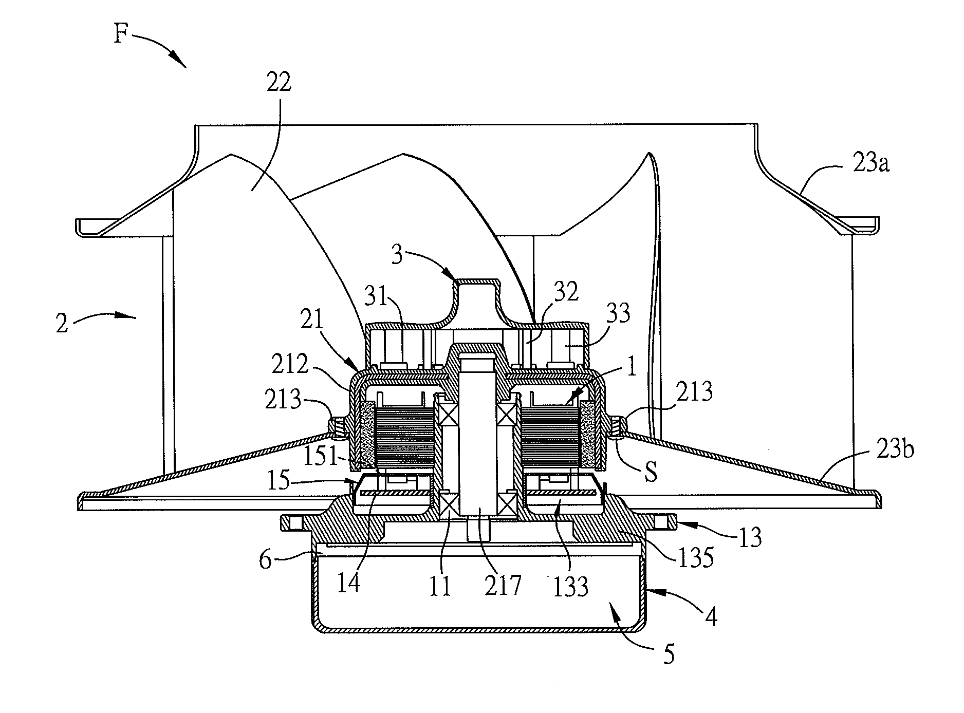
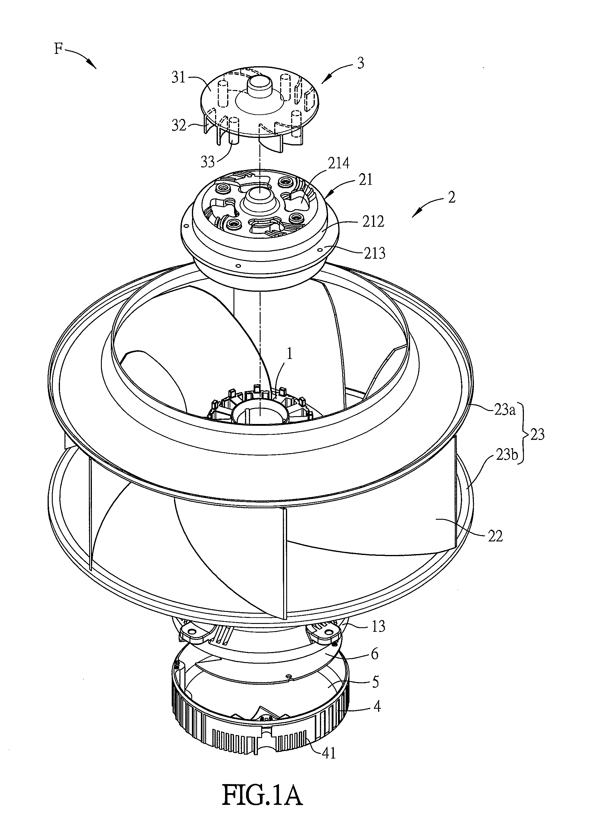
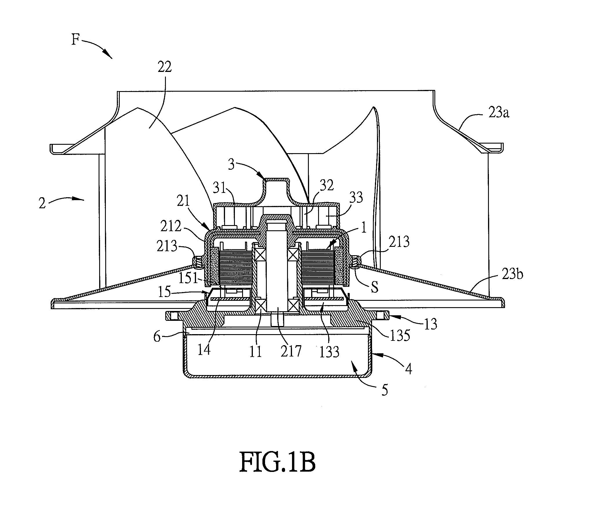
[0051]FIG. 1A is an exploded top view of a fan F according to a preferred embodiment of the invention, and FIG. 1B is a sectional view of the fan F of FIG. 1A. Referring to FIGS. 1A and 1B, the fan F includes a motor 1, an impeller 2 and a heat-dissipating structure 3. The impeller 2 includes a hub 21 and a plurality of outer blades (first blades) 22. The hub 21 has a hollow structure for receiving the motor 1. The hub 21 includes a top portion 211 and a side wall 212 disposed around the top portion 211 as shown in FIG. 2.

[0052]With reference to FIGS. 1A and 1B, the impeller 2 further includes two annular structures 23, and the outer blades 22 are disposed between the two annular structures 23. One of the annular structures 23 is connected to the side wall 212 of the hub 21. In this e...


PUM


Abstract

A fan includes a motor, an impeller and a heat-dissipating structure. The motor includes a stator magnet assembly, a frame, a first circuit board, and a cover. The frame supports the stator magnet assembly. The frame and the stator magnet assembly define a first accommodating space, and the first circuit board is disposed in the first accommodating space. The cover covers the first circuit board. The motor drives the impeller and the impeller includes a hub and a plurality of first blades. The hub has at least a heat-dissipating hole. The first blades are disposed around the hub, and the heat-dissipating structure is disposed at the outer side of the hub. The heat-dissipating structure has a baffle and at least a second blade extended from the baffle and located corresponding to the heat-dissipating hole.

Description

CROSS REFERENCE TO RELATED APPLICATIONS[0001]This Non-provisional application claims priority under 35 U.S.C. §119(a) on Patent Application No(s). 201310341962.9 and 201410197971.X filed in People's Republic of China on Aug. 7, 2013 and May 12, 2014, the entire contents of which are hereby incorporated by reference.BACKGROUND OF THE INVENTION[0002]1. Field of Invention[0003]The present invention relates to a fan and, in particular, to a fan with a heat-dissipating structure.[0004]2. Related Art[0005]In a typical fan structure, the impeller is disposed on the motor, and the motor can drive the impeller to rotate. Accordingly, the fan can generate proper airflow to bring the heat of the heating element away. Thus, the manufacturers try to design a fan that can increase the airflow quantity as much as possible. To increase the rotation speed of a fan is a general method for enlarging the airflow quantity, but the rotation speed of a fan has physical limitation in practice. Because the ...

Claims


Application Information

Patent Timeline
Patent Type & Authority Applications(United States)
IPC IPC(8): F04D29/58F04D25/06
CPCF04D25/0613F04D29/5806F04D17/16F04D25/082
Inventor HUANG, SHIH-HANCHANG, SHUN-CHEN
Owner DELTA ELECTRONICS INC
Why Eureka
Try Eureka