Fan

a technology of fan and fan body, which is applied in the direction of non-positive displacement fluid engines, pump components, piston pumps, etc., can solve the problems of large burden on the structure and bearings of the motor, inability to raise the rotation speed unlimitedly, and inability to reduce the noise of the surrounding region, so as to reduce the stagnant region and the noise of the accompanying noise, the effect of lowering the temperature of the bearing

Active Publication Date: 2015-02-12
DELTA ELECTRONICS INC
View PDF8 Cites 6 Cited by
  • Summary
  • Abstract
  • Description
  • Claims
  • Application Information

AI Technical Summary

Benefits of technology

The invention provides a fan with a heat dissipating structure for the motor, which helps to effectively dissipate the heat generated during operation. This results in a safer and longer lifespan for the motor and fan. The heat dissipating structure is designed to rotate with the fan, creating a convection effect to remove the heat through the heat dissipating holes. The second airflow generated by the inner blades also helps to reduce noise and power consumption. Additionally, the placement of the heat dissipating holes decreases the total weight of the hub.

Problems solved by technology

However, when the fan rotates at a high speed, the blades of the fan will bear extremely high pressure and may be thus deformed and even broken, resulting in a very dangerous situation.
Thus, the rotation speed can not be raised unlimitedly in the design of the fan.
Besides, at the high-speed rotation, the motor's structure and bearings will be subjected to a large burden, which heavily threatens the lifespan of the product.
Moreover, because the motor is disposed within the impeller, the heat generated by the motor can not be smoothly dissipated due to the impediment of the impeller.
In this situation, the bearings of the motor will be easily damaged and the lifespan of the motor is thus reduced.
Furthermore, some fans that can generate high airflow pressure, such as centrifugal fans, are commonly applied to a heat dissipating apparatus of a complex system, such as a communication cabinet or a frequency converter cabinet, and these heat dissipating apparatuses will generate an environment up to 70° C. The temperature of the motor operating in the 70° C. environment will reach 100° C., which will reduce the lifespan of the motor's bearing a lot.

Method used


Image

  • Fan
  • Fan
  • Fan

Examples


Embodiment Construction

[0034]The present invention will be apparent from the following detailed description, which proceeds with reference to the accompanying drawings, wherein the same references relate to the same elements.

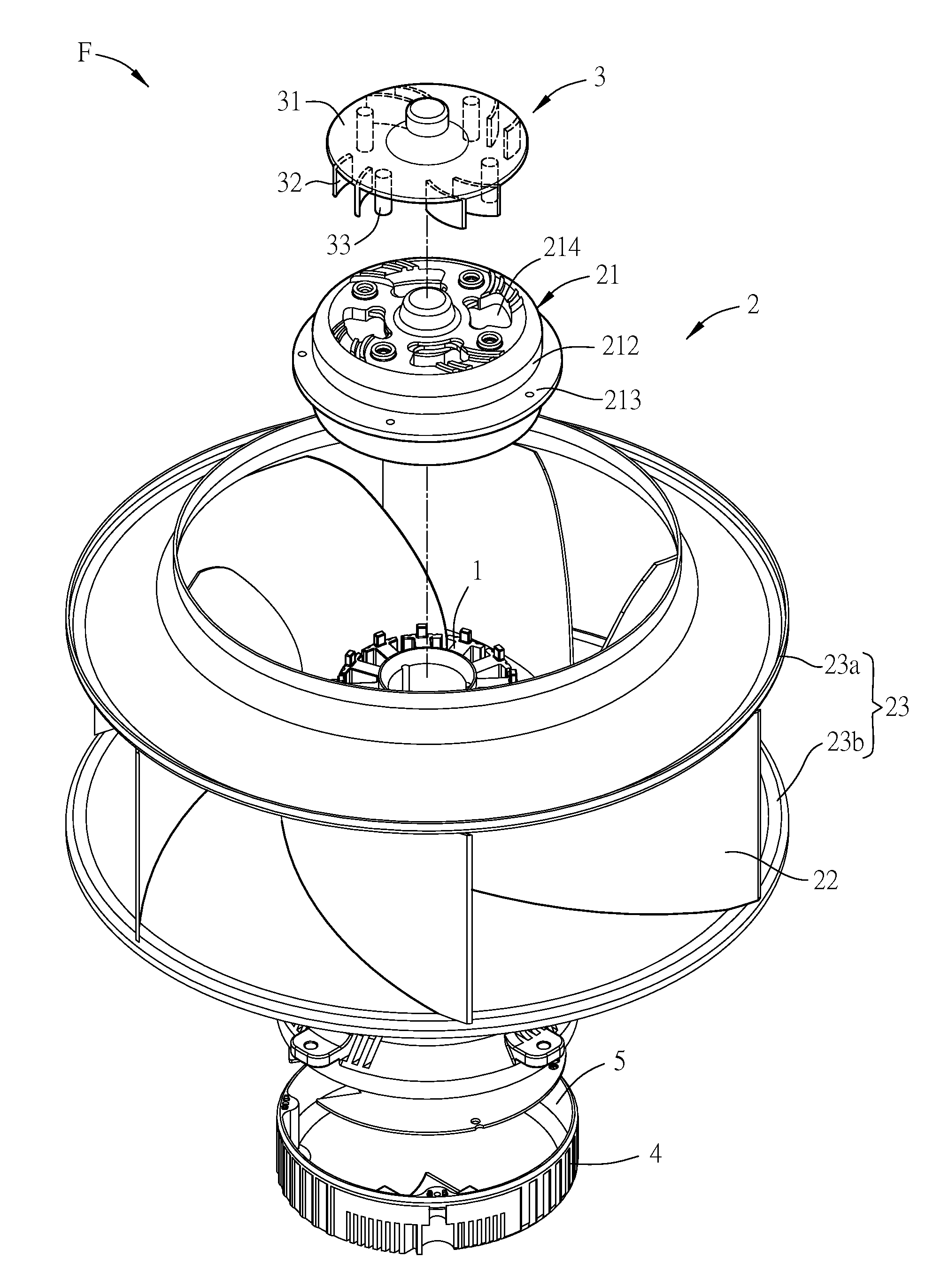
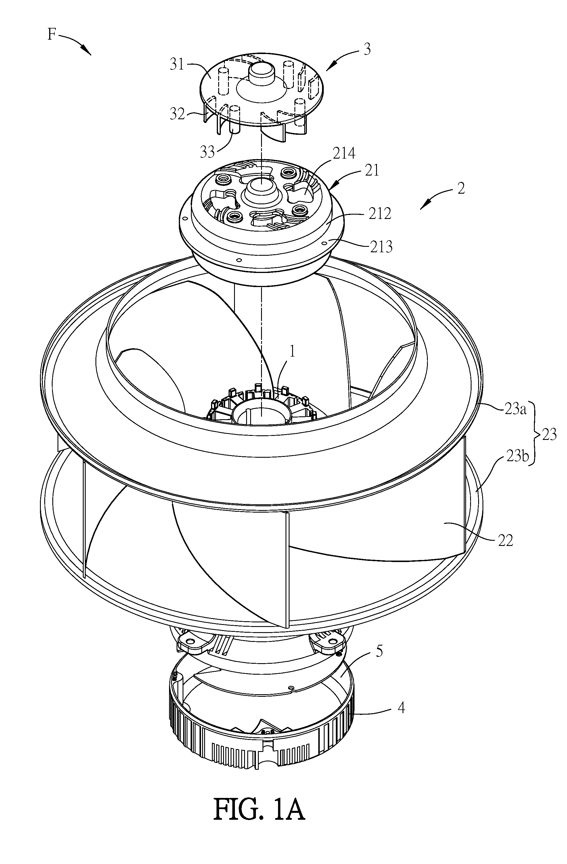
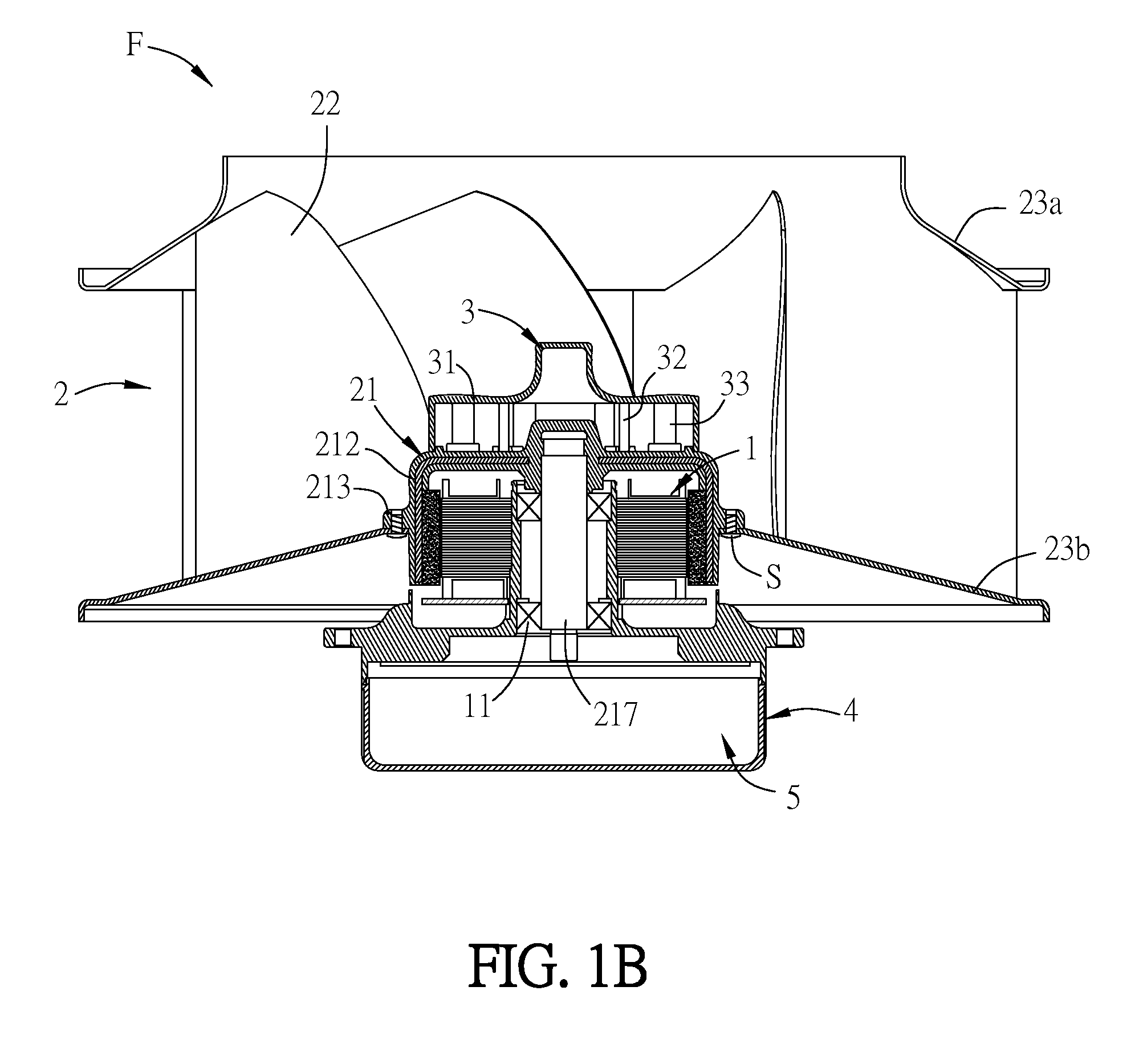
[0035]FIG. 1A is an exploded diagram of a fan according to an embodiment of the invention, and FIG. 1B is a schematic sectional diagram of the fan in FIG. 1A. As shown in FIGS. 1A and 1B, the fan F includes a motor 1, an impeller 2 and a heat dissipating structure 3. The impeller 2 includes a hub 21 and a plurality of outer blades (or called first blades) 22. The hub 21 is a hollow structure and can accommodate the motor 1. The hub 21 can be divided into a top portion 211 and a surrounding wall 212, as shown in FIG. 2. In FIGS. 1A and 1B, the impeller 2 further includes two annular structures 23, and the outer blades 22 are disposed between the annular structures 23. Besides, one of the annular structures 23 is connected to the surrounding wall 212 of the hub 21. In this embodiment, t...


PUM


Abstract

A fan includes a motor, an impeller and a heat dissipating structure. The impeller includes a hub and a plurality of first blades. The hub receives the motor, and the hub comprises at least a heat dissipating hole. The first blades are disposed around the hub. The heat dissipating structure is disposed outside the hub. The heat dissipating structure includes a baffle and at least a second blade extending from the baffle and disposed corresponding to the heat dissipating hole.

Description

CROSS REFERENCE TO RELATED APPLICATIONS[0001]This Non-provisional application claims priority under 35 U.S.C. §119(a) on Patent Application No(s). 201310341962.9 filed in People's Republic of China on Aug. 7, 2013; the entire contents of which are hereby incorporated by reference.BACKGROUND OF INVENTION[0002]1. Field of Invention[0003]The invention relates to a fan and, in particular, to a fan having a heat dissipating structure.[0004]2. Related Art[0005]In a general structure of a fan, the impeller is coupled to the motor and driven by the motor to rotate so as to supply sufficient airflow volume to the heat generating device or space for the purpose of heat dissipation. So, the current fan designers and manufacturers make efforts in the kind of fan that can provide more airflow. One way to increase the airflow of the fan is to raise the rotation speed of the fan. However, when the fan rotates at a high speed, the blades of the fan will bear extremely high pressure and may be thus ...

Claims


Application Information

Patent Timeline
IPC IPC(8): F04D25/08
CPCF04D25/082F04D29/5806F04D29/584F04D25/166F04D29/281
Inventor HUANG, SHIH-HANCHANG, SHUN-CHEN
Owner DELTA ELECTRONICS INC
Why Eureka
Try Eureka