Fluidic system, use, and method for operating the same

a technology of fluidic system and membrane, applied in the field of fluidic system, can solve the problems of uncontrolled liquid transport, uncontrolled liquid transport, unwanted liquid residues on and in the membrane, etc., and achieve the effect of improving the efficiency of the exchange process

Active Publication Date: 2015-02-19
FRAUNHOFER GESELLSCHAFT ZUR FOERDERUNG DER ANGEWANDTEN FORSCHUNG EV
View PDF0 Cites 8 Cited by
  • Summary
  • Abstract
  • Description
  • Claims
  • Application Information

AI Technical Summary

Benefits of technology

This patent text describes a method for improving the efficiency of a membrane to transfer fluids using electro-wetting. The method involves switching between different states to change the wetting of the membrane surface, which allows for a more secure process management. The fluidic system used in this method does not have any moving parts, reducing wear and tear. The technical effect of this patent is a more efficient and secure method for transferring fluids using electro-wetting.

Problems solved by technology

Depending on the application, it may be a drawback in this or similar systems that the membranes due to the wetting behavior hinder the transport of the liquid upon entering or leaving the membrane so much that high pressures or pressure differences are needed under such alternating drying, wetting, and drying.
In many applications, the required pressure differences cannot be produced in a microfluidic system or the membranes cannot withstand them mechanically or a breakthrough of the liquid through the membrane results in an uncontrolled liquid transport.
Furthermore, it can happen that the capillary channels in event of a breakthrough are not necessarily completely emptied, so that unwanted liquid residues remain on and in the membrane.

Method used


Image

  • Fluidic system, use, and method for operating the same
  • Fluidic system, use, and method for operating the same
  • Fluidic system, use, and method for operating the same

Examples


Embodiment Construction

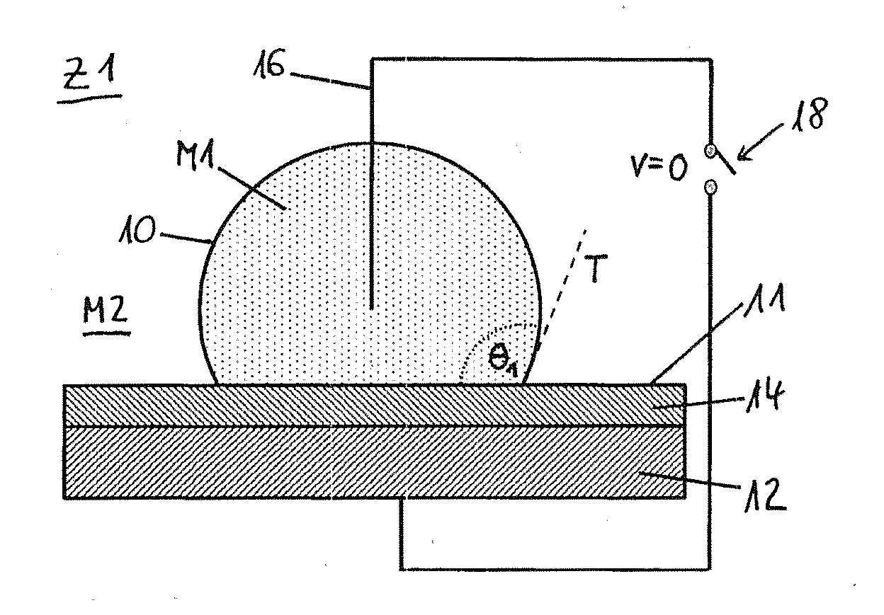
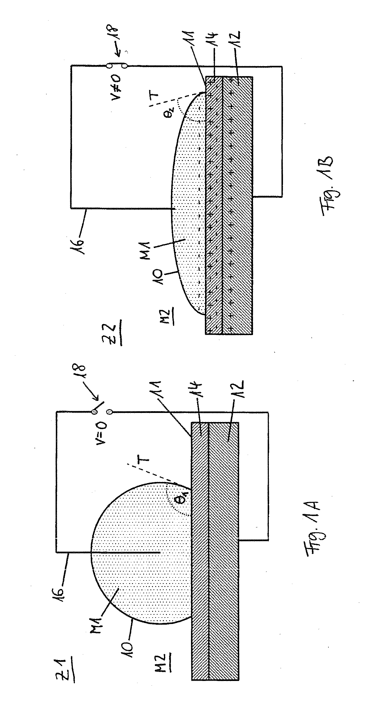
[0085]By means of FIGS. 1A and 1B, the wetting behavior is described between a first medium M1, such as a liquid drop, and a second medium M2, such as a gas surrounding the liquid drop, and a surface 11 of a body which is being wetted. In order to change the wetting behavior, one makes use of the phenomenon of electro-wetting. The surface 11 of the body being wetted has, for this purpose, an electrically conducting substrate 12, forming a first electrode, on which a layer of a dielectric 14 is deposited. A second electrode 16 is dipped directly into the first medium M1. The electrodes 12 and 16 are connected to a voltage source 18.

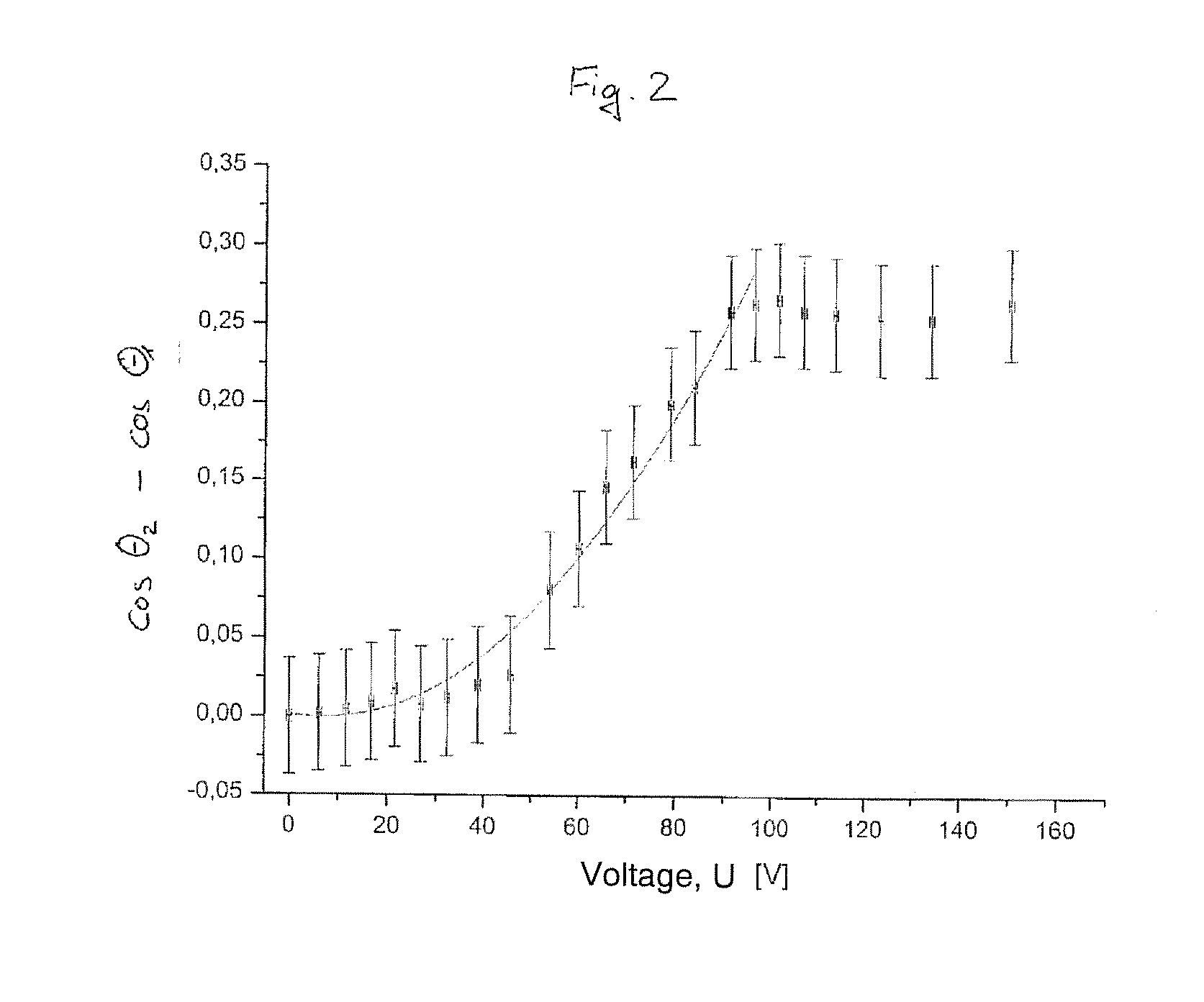
[0086]FIG. 1A shows a state Z1 in which the surface 10 is less wetted by the first medium M1, so that a first contact angle θ1>90° is formed. Between the electrodes 12 and 16 no voltage exists. In state Z1, the electric field is therefore E1=0 V / m.

[0087]FIG. 1B describes a state Z2 in which a voltage is imposed between the two electrodes 12 and 16. This pr...


PUM

PropertyMeasurementUnit
Temperatureaaaaaaaaaa
Dielectric polarization enthalpyaaaaaaaaaa
Pressureaaaaaaaaaa

Abstract

A fluidic system having a first volume, a second volume and a membrane geometrically separating the two volumes, which has an open-pore microstructure for the passage of a first medium and a second medium. There is a contact angle (θ) between the interface of the media and the pore surface. A first electrical field in the region of the membrane and a first electromagnetic radiation and a first heating of the membrane define a first state (Z1), in which the membrane is not wetted or is less wetted by the first medium and is more heavily wetted by the second medium such that a first contact angle θ1>90° is formed between the pore surface and the interface. The first medium and the second medium and the pore surface have a surface energy of which at least one surface energy can be reversibly changed in such a way that a second contact angle θ2<θ1 occurs between the pore surface and the interface in a second state (Z2).

Description

FIELD OF THE INVENTION[0001]The invention concerns a fluidic system, especially a microfluidic system, with a first volume, a second volume, and a membrane geometrically separating the two volumes, which provides an open-pore microstructure with a pore surface for the passage of a first medium and a second medium, between which a boundary surface is formed, while a contact angle exists between the boundary surface and the pore surface. The invention moreover concerns the use of a fluidic system and a method for its operation.[0002]A “fluidic system” in the sense of this document is composed of at least three components: a shape-stable, bodily arrangement, i.e., a solid, a first medium or fluid, and a second medium or fluid. The solid contains a substrate in which one or more fluidic lines are incorporated, and a membrane separating the fluidic line spatially into two segments, namely, the first and the second volume.[0003]By “volume” in the sense of the present document is generally...

Claims


Application Information

Patent Timeline
IPC IPC(8): F16K99/00B01D61/18B01D61/22B01D35/06
CPCF16K99/0017B01D35/06F16K99/0042B01D61/22F16K99/004B01D61/18B01L3/502715B01L3/502738B01L3/502746B01L3/502769B01L2200/0673B01L2200/146B01L2300/0681B01L2300/161B01L2400/0427B01L2400/088F16K99/0025F16K2099/0084G02B26/005Y10T137/2191Y10T137/2196
Inventor BASSLER, MICHAELDRESE, KLAUS STEFANLATTA, DANIEL
Owner FRAUNHOFER GESELLSCHAFT ZUR FOERDERUNG DER ANGEWANDTEN FORSCHUNG EV
Why Eureka
Try Eureka