Semi-automatic welding system, conversion adapter kit, and welding torch

Inactive Publication Date: 2015-02-19
NIPPON SANSO CORP
View PDF4 Cites 18 Cited by
  • Summary
  • Abstract
  • Description
  • Claims
  • Application Information

AI Technical Summary

Benefits of technology

[0057]As described above, according to the present invention, a non-consumable electrode type semi-automatic welding system to which at least one part of a consumable electrode type semi-automatic welding system is applied and which can conduct a welding at a high speed having

Problems solved by technology

Therefore, when welding is conducted on a thick object to be welded, because an amount

Method used


Image

  • Semi-automatic welding system, conversion adapter kit, and welding torch
  • Semi-automatic welding system, conversion adapter kit, and welding torch
  • Semi-automatic welding system, conversion adapter kit, and welding torch

Examples


example 1

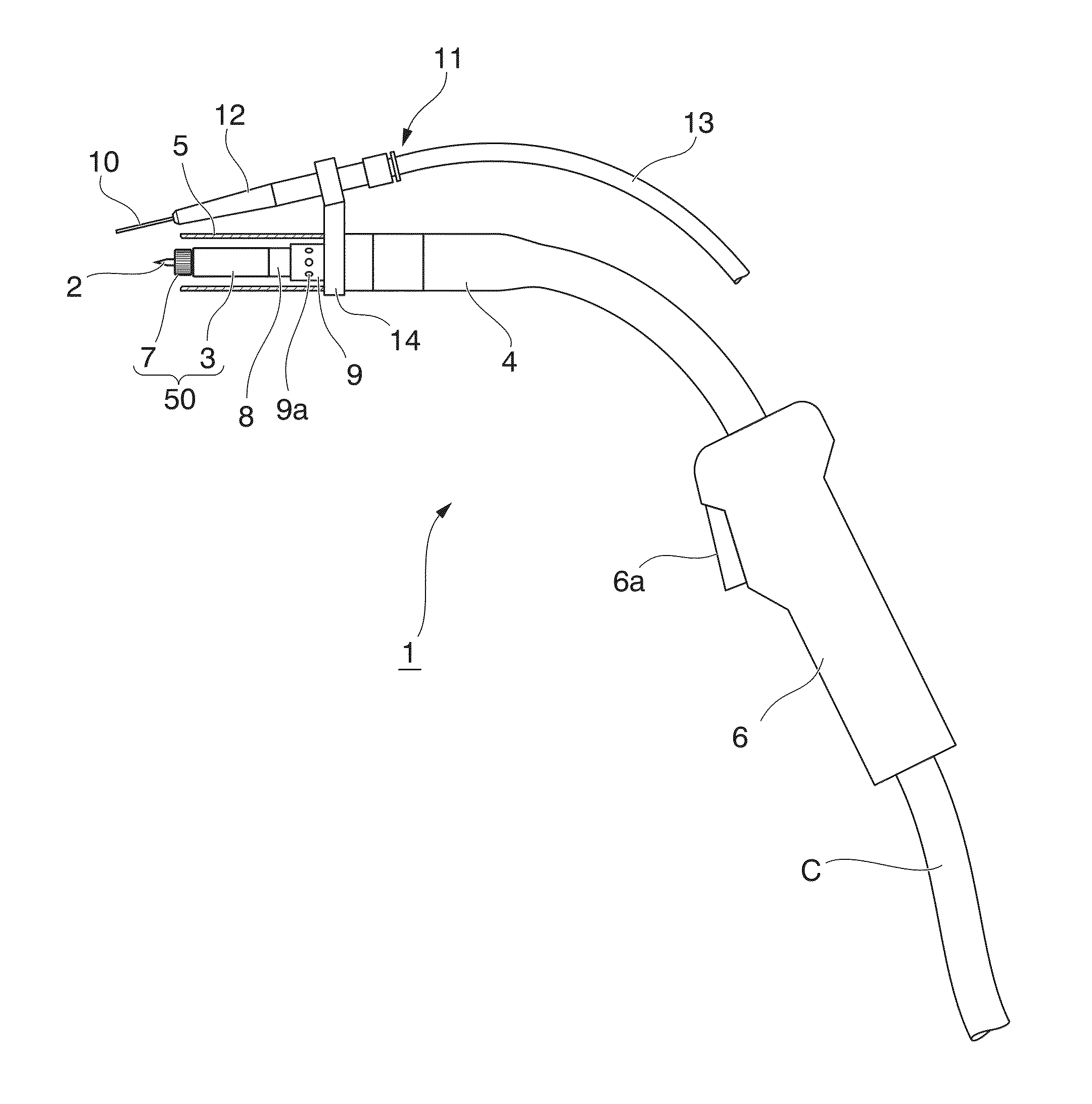
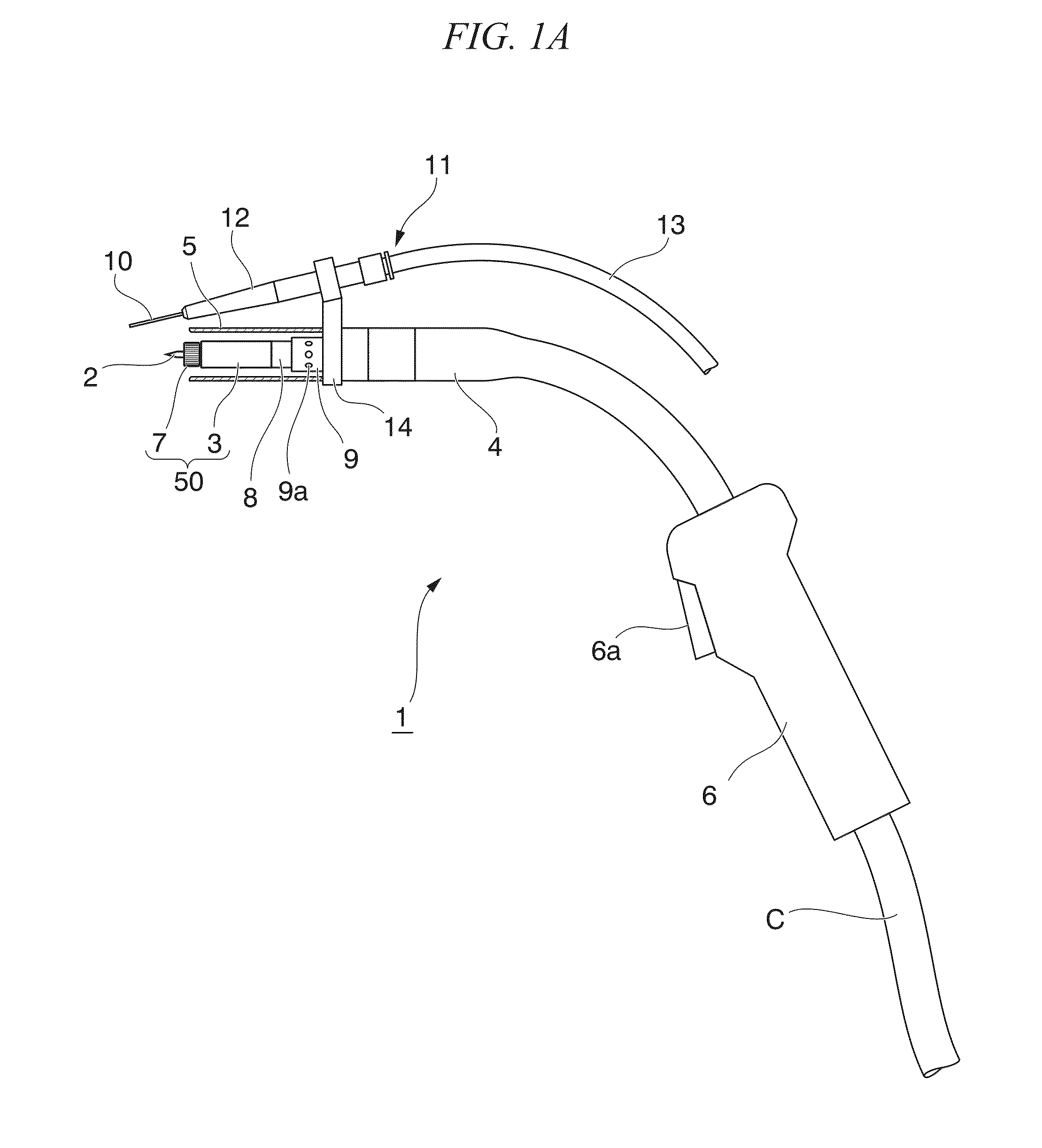
[0174]In Example 1, a butt welding was actually conducted using the welding torch 1 shown in FIG. 1A and FIG. 1B. The welding conditions are as follows. Material of object to be welded: SUS304 (austenite stainless steel), sheet thickness of 12 mm

[0175]Shield gas: mixed gas of 93% Ar gas and 7% H2 gas (Condition 1), 100% Ar gas (Condition 2)

[0176]Non-consumable electrode: tungsten electrode bar, diameter of 3.2 mm

[0177]Electric current: peak current of 350 A, base current of 200 A, pulse frequency of 30 Hz

[0178]Welding wire: SUS308L, diameter of 1.6 mm, delivering speed of 3.5M / min

[0179]Then, photographs after welding are shown in FIG. 10. A photograph of left side in FIG. 10 is the case of Condition 1 and a photograph of right side in FIG. 10 is the case of Condition 2.

[0180]As shown in FIG. 10, the welded part was a beautiful end result with no welding defect.

example 2

[0181]In Example 2, a horizontal fillet welding was actually conducted using the welding torch 1 shown in FIG. 1A and FIG. 1B. The welding conditions are as follows. Material of object to be welded: UNS S32750 (two-phase stainless steel), sheet thickness of 8 mm

[0182]Shield gas: mixed gas of 50% Ar gas and 50% He gas (Condition 1), mixed gas of 93% Ar gas and 7% H2 gas (Condition 2)

[0183]Non-consumable electrode: tungsten electrode bar, diameter of 4.0 mm

[0184]Electric current: peak current of 320 A, base current of 300 A, pulse frequency of 30 Hz

[0185]Welding wire: 329J4L, diameter of 1.2 mm, delivering speed of 6M / min

[0186]Then, photographs after welding are shown in FIG. 11. A photograph of left side in FIG. 11 is the case of Condition 1 and a photograph of right side in FIG. 11 is the case of Condition 2.

[0187]As shown in FIG. 11, the welded part was a beautiful end result with no welding defect.

example 3

[0188]In Example 3, horizontal fillet welding was actually conducted using the semi-automatic welding torch 1 shown in FIG. 1A and FIG. 1B and the manually-powered TIG welding torch 100 shown in FIG. 13A and FIG. 13B and the comparison was conducted.

[0189]Welding conditions regarding the semi-automatic welding torch 1 shown in FIG. 1A and FIG. 1B are as follows.

[0190]Material of object to be welded: SUS304 (austenite stainless steel), sheet thickness of 10 mm

[0191]Shield gas: mixed gas of 50% Ar gas and 50% H2 gas

[0192]Non-consumable electrode: tungsten electrode bar, diameter of 3.2 mm

[0193]Electric current: 300 A

[0194]Welding wire: SUS308L, diameter of 0.9 mm, delivering speed of 7.0M / min

[0195]On the other hand, welding conditions regarding the TIG welding torch 100 shown in FIG. 13A and FIG. 13B are as follows.

[0196]Material of object to be welded: SUS304 (austenite stainless steel), sheet thickness of 10 mm

[0197]Shield gas: mixed gas of 50% Ar gas and 50% H2 gas

[0198]Non-consuma...


PUM

PropertyMeasurementUnit
Fractionaaaaaaaaaa
Currentaaaaaaaaaa
Speedaaaaaaaaaa

Abstract

According to the present invention, a non-consumable electrode type semi-automatic welding system which can conduct welding with high weld deposit and high speed is provided. A welding torch (1), in which a non-consumable electrode (1) generating an arc between the non-consumable electrode and an object to be welded and a torch nozzle (5) ejecting a shield gas toward a welding pool of the object to be welded generated by the arc are provided; a wire feeder (502) which delivers a welding wire (10) toward the welding pool of the object to be welded from a tip end of a feeding head, the feeding head being mounted on the welding torch (1) via an attaching jig (14); and a welding power source (501) which supplies electric power and shield gas to the welding torch (1); are provided and one or more among the welding torch (1), the wire feeder (502), and the welding power source (501) are constituted by applying at least one part of a welding torch, wire feeder, and welding power source provided in a consumable electrode type semi-automatic welding system.

Description

TECHNICAL FIELD[0001]The present invention relates to a semi-automatic welding system, conversion adapter kit, and welding torch. The present application claims priority on the basis of Japanese Patent Application No. 2012-077309, filed in Japan on Mar. 29, 2012, the contents of which are incorporated herein by reference.BACKGROUND ART[0002]In welding of a structure (object to be welded) using metal or non-ferrous metal as a base material, a non-consumable-type gas-shielded arc welding called TIG welding (Tungsten Inert Gas welding) or GTAW welding (Gas Tungsten Arc welding) such as plasma arc welding has been conventionally used.[0003]Also, a consumable-type gas-shielded arc welding called MIG welding (Metal Inert Gas welding), MAG welding (Metal Active Gas welding), or GMAW (Gas Metal Arc welding) such as carbon dioxide arc welding has been used. The consumable-type gas-shielded arc welding, in which welding is manually conducted while a welding wire to become a consumable electro...

Claims


Application Information

Patent Timeline
IPC IPC(8): B23K9/29B23K9/167B23K9/26
CPCB23K9/296B23K9/167B23K9/26B23K2103/02
Inventor WADA, KATSUNORI
Owner NIPPON SANSO CORP
Why Eureka
Try Eureka