Unlock instant, AI-driven research and patent intelligence for your innovation.

Fresnel Lens Solar Concentrator Configured to Focus Sunlight at Large Longitudinal Incidence Angles onto an Articulating Energy Receiver

Active Publication Date: 2015-02-26
ONEILL MARK JOSEPH
View PDF2 Cites 18 Cited by
  • Summary
  • Abstract
  • Description
  • Claims
  • Application Information

AI Technical Summary

Benefits of technology

This invention is about a special lens that focuses sunlight onto a photovoltaic cell to convert it into electricity. The lens is made from a thin polymer film with microscopic prisms that mold into it. The lens is designed to maintain its shape in space and can be strengthened with cords or wires. The lens can also move closer or farther away from the energy receiver to maintain the best focus of sunlight. The prisms in the lens are carefully specified to provide good optical performance with a variety of solar incidence angles. The lens can be deployed and supported as a thin flexible membrane with tension. The technical effect of this invention is to improve the efficiency of photovoltaic cells and increase the amount of sunlight that can be converted into electricity.

Problems solved by technology

However, the previously patented version of SLA is substantially limited to relatively small (e.g., <15 degrees) longitudinal incidence angles of sunlight, typically called beta (β) angles in the space solar array industry.
For many missions, however, the longitudinal incidence angles (β angles) can be relatively large, and the existing SLA technology will not work well for such missions.
The existing SLA will not provide an acceptable focus of sunlight for such large β angles.
New multi-junction solar cells are being developed with four junctions and six junctions to improve the solar-to-electric conversion efficiency, but such cells are very expensive with projected costs of more than $10 per square centimeter of cell area.

Method used


Image

  • Fresnel Lens Solar Concentrator Configured to Focus Sunlight at Large Longitudinal Incidence Angles onto an Articulating Energy Receiver
  • Fresnel Lens Solar Concentrator Configured to Focus Sunlight at Large Longitudinal Incidence Angles onto an Articulating Energy Receiver
  • Fresnel Lens Solar Concentrator Configured to Focus Sunlight at Large Longitudinal Incidence Angles onto an Articulating Energy Receiver

Examples


Embodiment Construction

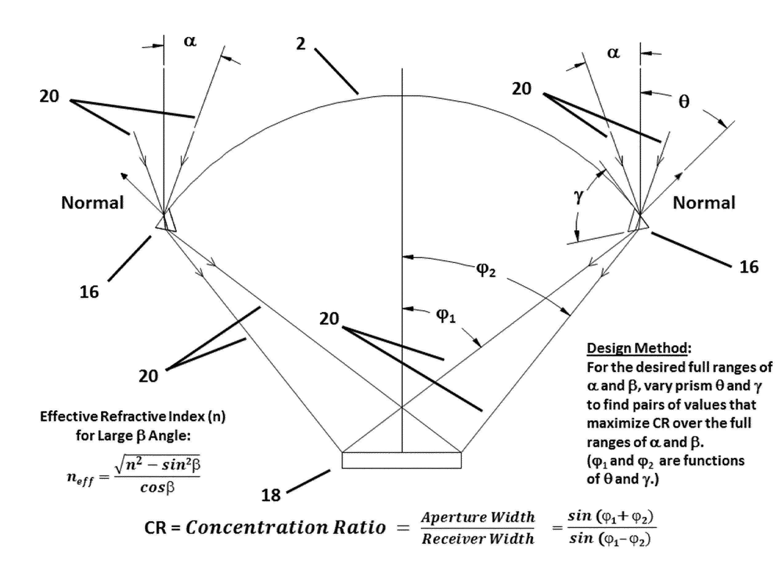
[0020]The present invention is best understood by referring to the attached drawings, which shows a preferred embodiment. Referring to FIG. 1, the arch-shaped linear Fresnel lens 2 is configured in its shape and in the geometry of the prisms on its inner surface to focus incident solar rays onto an articulating narrower energy receiver while the system operates under a variety of different longitudinal solar ray angles of incidence (β angles). When the β angle is 0 degrees, the energy receiver 4 is positioned at its greatest distance from lens 2 so that solar rays 6 are focused properly onto receiver 4. When the β angle is 25 degrees, the energy receiver 8 is positioned closer to lens 2 so that solar rays 10 are focused properly onto receiver 8. When the β angle is 50 degrees, the energy receiver 12 is positioned still closer to lens 2 so that the solar rays 14 are properly focused onto receiver 12. The configuration of the lens 2 must be designed using analytical ray trace models t...


PUM


Abstract

This invention includes a Fresnel lens assembly positioned relative to an energy receiver, onto which the lens assembly focuses sunlight for collection and conversion. The Fresnel lens assembly includes a thin polymeric film with prisms molded into or attached to the film. This invention also includes an articulating energy receiver which can move closer to or farther away from the lens depending on the longitudinal angle of incidence of the sunlight relative to the lens, to maintain the best focus of sunlight on the energy receiver. The prisms in the present lens are specified to provide acceptable optical performance in the presence of relatively large longitudinal solar incidence angles, relatively smaller lateral solar incidence angles, in combination with the articulating energy receiver. The new lens assembly can further be deployed and supported as a thin flexible stretched membrane with tension maintaining the lens in proper position on orbit.

Description

CROSS REFERENCE TO RELATED APPLICATION[0001]The present non-provisional application for patent was previously submitted to the U.S. Patent and Trademark Office as a provisional application, Application No. 61 / 696,199, Attorney Docket No. mjo003, filed on Sep. 2, 2012, with Confirmation No. 6728. The title, inventor, and disclosed invention were the same for the earlier provisional application as for this present non-provisional application. The inventor hereby claims the filing date of the earlier provisional application, namely Sep. 2, 2012.[0002]INVENTOR: Mark J. O'Neill, Keller, Tex.BACKGROUND[0003]The present inventor previously invented the Stretched Fresnel Lens for Space Power, as described in U.S. Pat. No. 6,075,200 (Reference 1). NASA and the U.S. Department of Defense have recognized the many advantages of this Stretched Lens Array (SLA) technology for space power, and have funded a number of R&D contracts totaling about $10,000,000 to develop, test, mature, and fly SLA te...

Claims


Application Information

Patent Timeline
IPC IPC(8): H01L31/052F24S20/20F24S23/30
CPCH01L31/0524H01L31/0543B64G1/443F24S23/31F24S2020/23G02B3/08Y02E10/52
Inventor O'NEILL, MARK JOSEPH
Owner ONEILL MARK JOSEPH