High frequency circuit and high frequency module including the same
a high frequency circuit and high frequency module technology, applied in the direction of low noise amplifiers, amplifier modifications to reduce non-linear distortion, baseband system details, etc., can solve the problems of increasing pa power consumption, increasing material cost, and affecting the effect of transmission signal distortion
- Summary
- Abstract
- Description
- Claims
- Application Information
AI Technical Summary
Benefits of technology
Problems solved by technology
Method used
Image

Examples
first embodiment
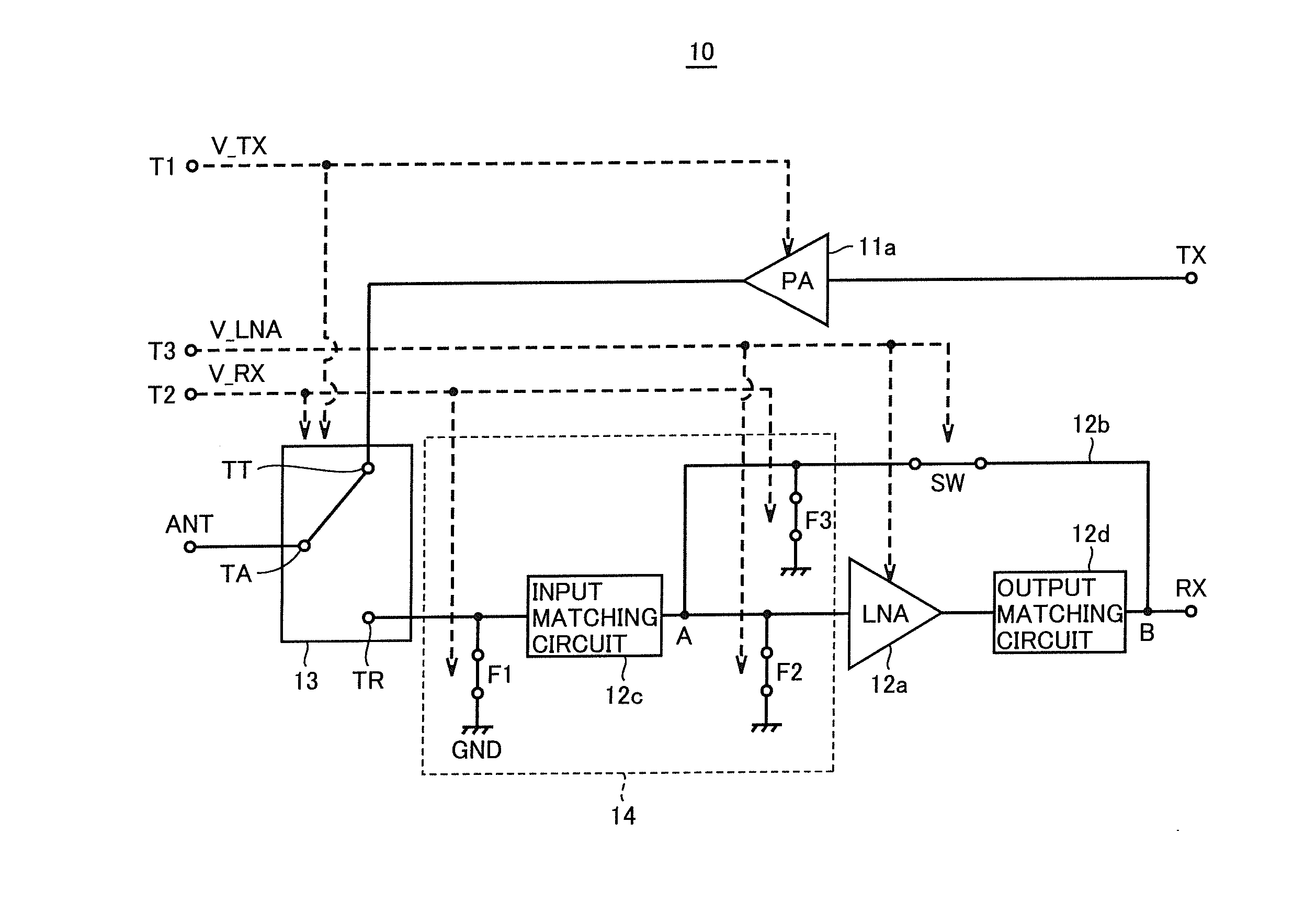
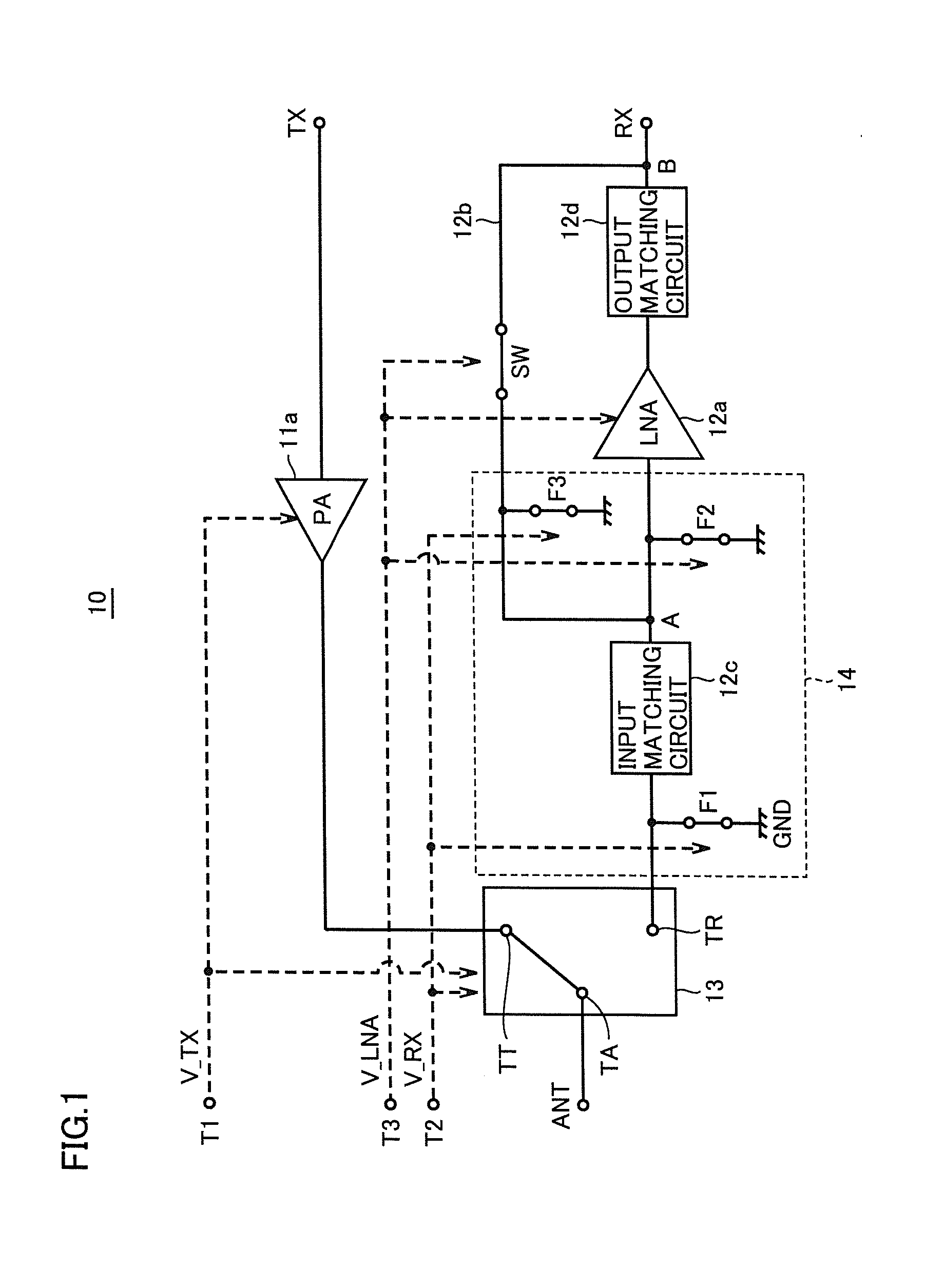
[0065]FIG. 1 is a circuit block diagram illustrating the configuration of a front-end circuit according to a first embodiment of the present invention.
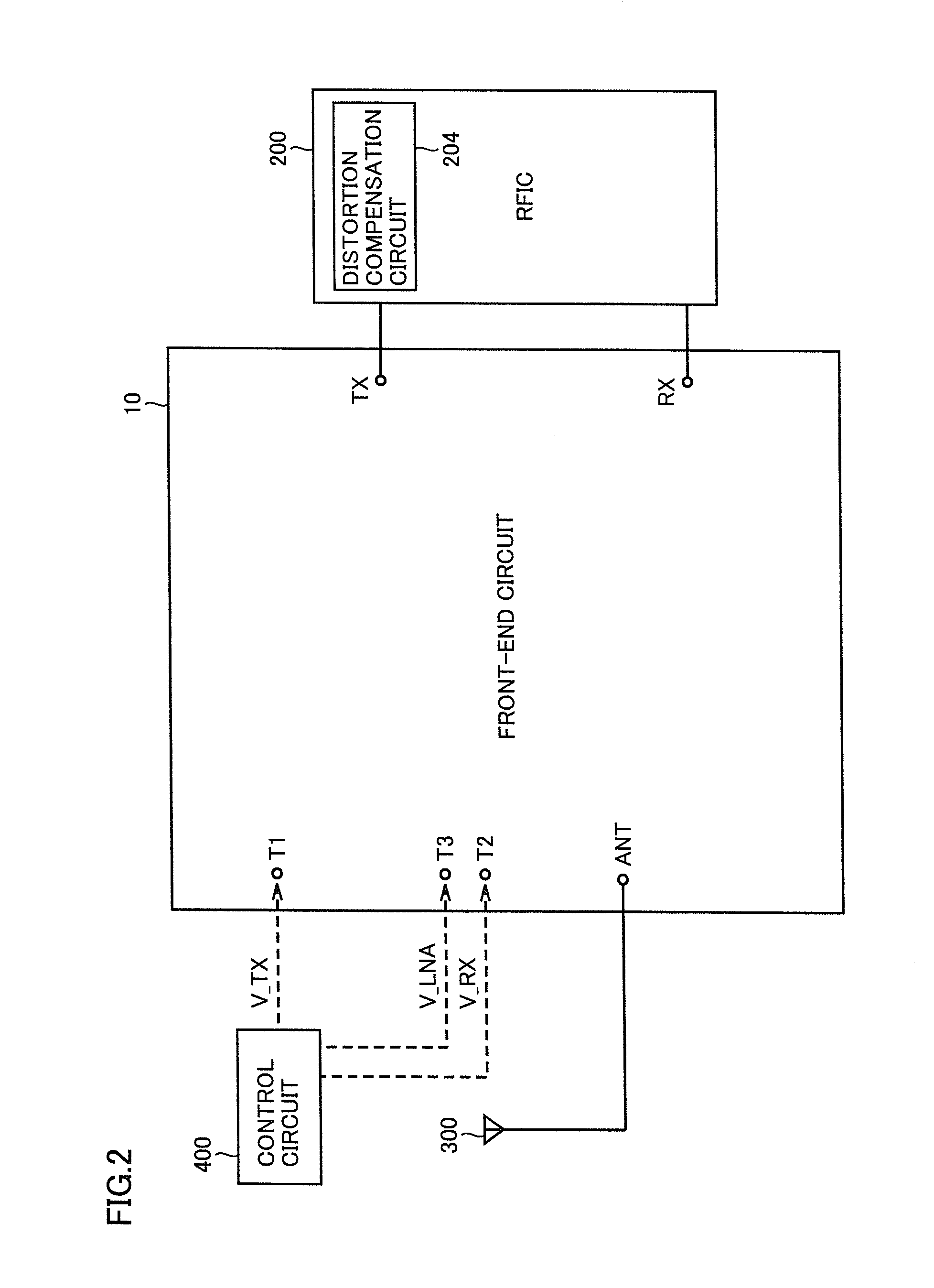
[0066]FIG. 2 is a circuit block diagram illustrating the connection of the front-end circuit illustrated in FIG. 1 to an external circuit.
[0067]With reference to FIGS. 1 and 2, a front-end circuit 10 is provided with a PA (power amplifier circuit) 11a, an LNA (low noise amplifier circuit) 12a, a bypass circuit 12b, an input matching circuit 12c, an output matching circuit 12d, an antenna switch (connection switching circuit) 13, an attenuation unit 14 (excluding input matching circuit 12c), a transmission terminal TX, a reception terminal RX, an antenna terminal ANT, and control terminals T1 to T3.
[0068]PA 11a and LNA 12a each is an amplifier circuit for amplifying a weak input signal and outputting the signal after amplification. PA 11a amplifies a signal received by transmission terminal TX. The signal amplified by PA 11a is output ...
second embodiment
[0123]The second embodiment is different from the first embodiment in that attenuation unit 14 includes two attenuation circuits. In the second embodiment, the description will be carried out on that attenuation unit 14 includes two attenuation circuits provided at two positions, respectively.
[0124]FIG. 10 is a circuit block diagram illustrating the configuration of a front-end circuit according to the second embodiment of the present invention. With reference to FIG. 10, in front-end circuit 20, attenuation circuit F1 (first attenuation circuit) is provided between antenna switch 13 and start point A, and attenuation circuit F2 (second attenuation circuit) is provided between start A and LNA 12a. Attenuation circuit F1 is wired to receive control signal V_RX. Attenuation circuit F2 is wired to receive control signal V_LNA.
[0125]In the second embodiment, one attenuation circuit is provided immediately before LNA 12a. Thereby, according to the second embodiment, especially in the cas...
third embodiment
[0126]The third embodiment is different from the second embodiment in the arrangement of the two attenuations. However, in the third embodiment, attenuation unit 14 includes two attenuation circuits provided at two positions, respectively, which is the same as the second embodiment.
[0127]FIG. 11 is a circuit block diagram illustrating the configuration of a front-end circuit according to the third embodiment of the present invention. With reference to FIG. 11, in front-end circuit 30, attenuation circuit F1 (first attenuation circuit) is provided between antenna switch 13 and start point A, and attenuation circuit F2 (second attenuation circuit) is provided between start A and switch SW.
[0128]In the third embodiment, one attenuation circuit is provided immediately before switch SW. Thereby, according to the third embodiment, especially in the case where the switching transistor included in switch SW is mainly responsible for causing a distortion to occur in the loopback signal, the ...
PUM
 Abstract
Description
Claims
Application Information