Methods for forming vias in glass substrates

Active Publication Date: 2015-03-05
CORNING INC
View PDF3 Cites 69 Cited by
  • Summary
  • Abstract
  • Description
  • Claims
  • Application Information

AI Technical Summary

Benefits of technology

[0010]In another embodiment, a method of forming a through via in a glass substrate includes laser drilling the through via through a thickness of the glass substrate from an incident surface to an exit surface of the glass substrate, such that the through via extends between an incident opening of the incident surface of the glass substrate and an exit opening of the exit surface of the glass substrate. The method further includes applying an acid-resistant film to the incident surf

Problems solved by technology

FRP interposers may suffer from a variety of drawbacks.
For example, cylindrical vias may be formed in FRP interposers by drilling with undesirably expensive fine drill bits.
Such drill bits may wander on the surface of the substrate, thereby limiting hole diameter and pitch.
Furthermore, the coefficient of thermal expansion (“CTE”) of FRP interposers may be about five times greater than that of

Method used


Image

  • Methods for forming vias in glass substrates
  • Methods for forming vias in glass substrates
  • Methods for forming vias in glass substrates

Examples


example a-1

[0048]In this control example, four glass samples were etched without ultrasonic agitation. Four samples of Eagle XG© glass were obtained. Through via pilot holes were drilled through the glass samples using a laser beam. The thicknesses of the samples were first measured and recorded. The samples were etched in a one liter solution of HF and HNO3 using mechanical agitation but no ultrasonic application for a specified amount of time. The etch solution temperature was about 25±2° C. After thoroughly washing and drying the samples, the post etch thicknesses of the samples were measured again. To determine the hole quality and shape, the diameters of the holes on the incident surface (also referred to as entry holes), their waist diameters (e.g., the diameter halfway between the incident surface and exit surface), and the exit surface diameters were measured. Table 1, below, shows average diameter and average circularity for entry holes, exit holes, and waists for the vias of each of ...

example a-2

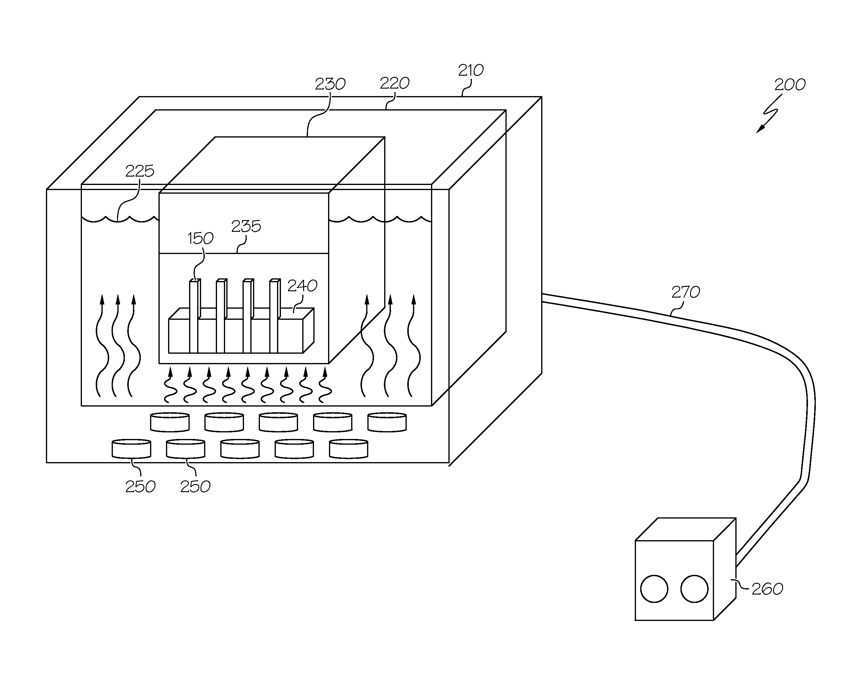
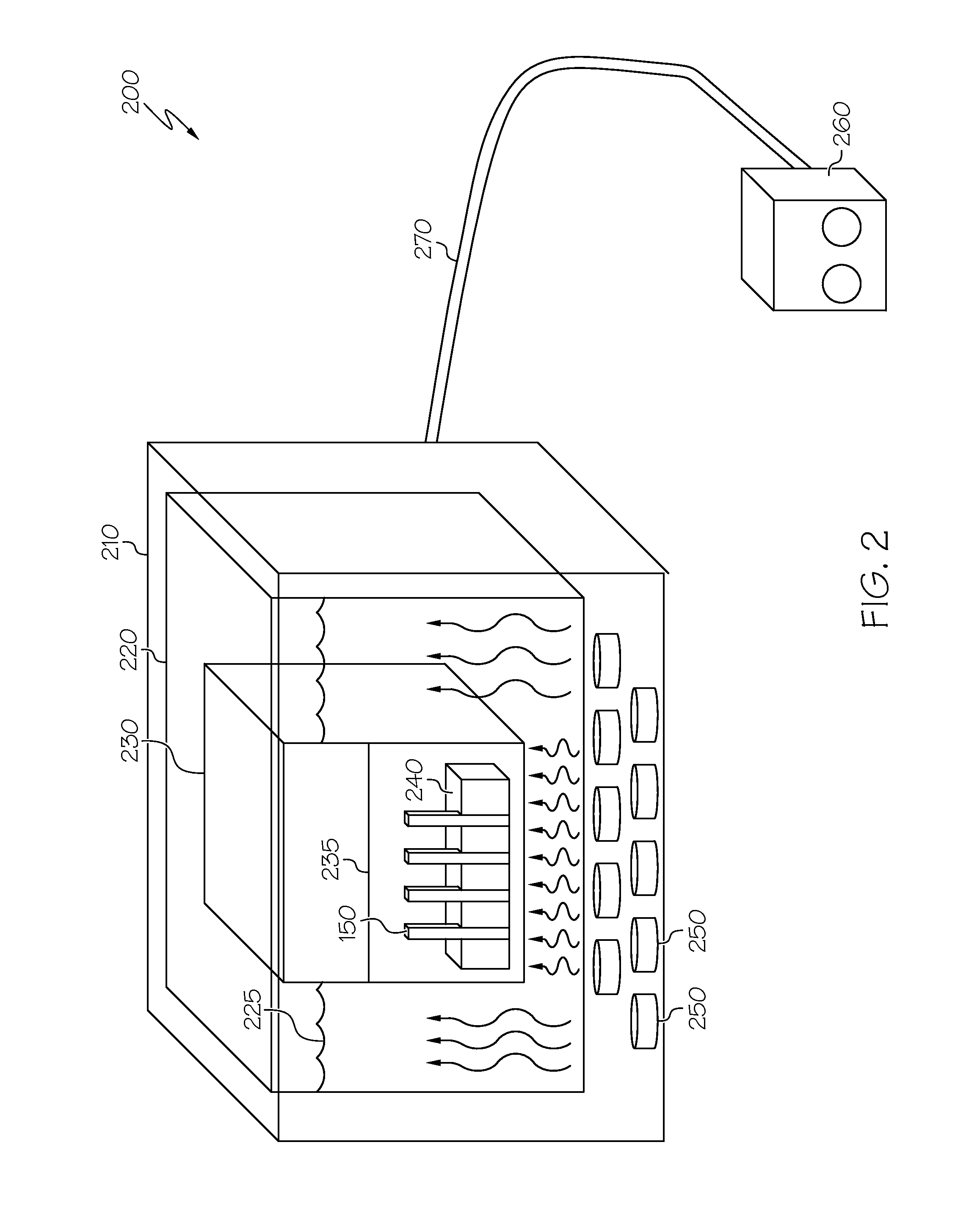
[0049]At least two samples of Eagle XG© glass were obtained. Through via pilot holes were drilled through the glass samples using a laser beam. After obtaining the thicknesses of the samples, they were etched in a one liter solution of HF and HNO3 in the presence of a 40 kHz ultrasonic field. The samples were also mechanically agitated. The initial etch solution temperature was about 25±2° C. After thoroughly washing and drying the samples, the post etch thicknesses of the samples were measured again. To determine the hole quality and shape, the diameters of the holes on the incident surface, their waist diameters, and the exit surface diameters were measured. The “40 kHz” column of Table 2, below, shows the measurements and evaluations (e.g., number of chipped entry holes, number of through holes that extended through the glass sample, etc.) for this example.

example a-3

[0050]At least two samples of Eagle XG© glass were obtained. Through via pilot holes were drilled through the glass samples using a laser beam. After obtaining the thicknesses of the samples, they were etched in a one liter solution of HF and HNO3 in the presence of a 132 kHz ultrasonic field. The samples were also mechanically agitated. The initial etch solution temperature was about 25±2° C. After thoroughly washing and drying the samples, the post etch thicknesses of the samples were measured again. To determine the hole quality and shape, the diameters of the holes on the incident surface, their waist diameters, and the exit surface diameters were measured. The “132 kHz” column of Table 2, below, shows the measurements and evaluations (e.g., number of chipped entry holes, number of through holes that extended through the glass sample, etc.) for this example.


PUM

PropertyMeasurementUnit
Frequencyaaaaaaaaaa
Frequencyaaaaaaaaaa
Frequencyaaaaaaaaaa

Abstract

Methods for forming vias in glass substrates by laser drilling and acid etching are disclosed. In one embodiment, a method forming a via in a glass substrate includes laser drilling the via through at least a portion of a thickness of the glass substrate from an incident surface of the glass substrate. The method further includes etching the glass substrate for an etching duration to increase a diameter of an incident opening of the via and applying ultrasonic energy to the glass substrate during at least a portion of the etching duration. The applied ultrasonic energy has a frequency between 40 kHz and 192 kHz.

Description

CROSS-REFERENCE TO RELATED APPLICATIONS[0001]This application claims the benefit of priority under 35 U.S.C. §119 of U.S. Provisional Application Ser. No. 61 / 871,440 filed on Aug. 29, 2013 the content of which is relied upon and incorporated herein by reference in its entirety.BACKGROUND[0002]1. Field[0003]The present specification generally relates to methods for forming vias in glass substrates and, more specifically, to methods for forming vias in glass substrates by laser drilling and acid etching.[0004]2. Technical Background[0005]An interposer may be used as an electrical interface in an electronic device to spread an electrical connection to a wider pitch or to reroute a connection to a different connection. Typically, many thousands of vias (i.e., holes) are formed in the substrate of the interposer, which are subsequently filled with electrically conductive material and further processed in order to interface electrical connections. Interposers may be formed from a variety ...

Claims


Application Information

Patent Timeline
IPC IPC(8): H05K3/00C03C15/00
CPCC03C15/00H05K3/0035H05K3/0029H05K2203/0285H05K3/002C03C23/00C03C2218/34C03B33/0222B23K26/402B23K26/382B23K2103/54C03C23/0025B23K26/361B23K26/55H05K1/0306H05K3/0017B23K26/384B23K26/362B23K26/302B23K26/364
Inventor BURKETT, ROBERT CARLGOERS, UTA-BARBARAOWUSU, SAMUEL ODEIPETRIWSKY, TAMMY LYNN
Owner CORNING INC
Why Eureka
Try Eureka