Composite Blade Made by Additive Manufacturing

a technology of additive manufacturing and composite blades, which is applied in the field of composite blades of turbine machines, can solve the problems of increasing the cost of such blades and limited mechanical strength of such blades

Active Publication Date: 2015-03-05
TECHSPACE AERO
View PDF7 Cites 38 Cited by
  • Summary
  • Abstract
  • Description
  • Claims
  • Application Information

AI Technical Summary

Problems solved by technology

However, the mechanical strength of such a blade is limited.
In addition, its production re...

Method used


Image

  • Composite Blade Made by Additive Manufacturing
  • Composite Blade Made by Additive Manufacturing
  • Composite Blade Made by Additive Manufacturing

Examples


first embodiment

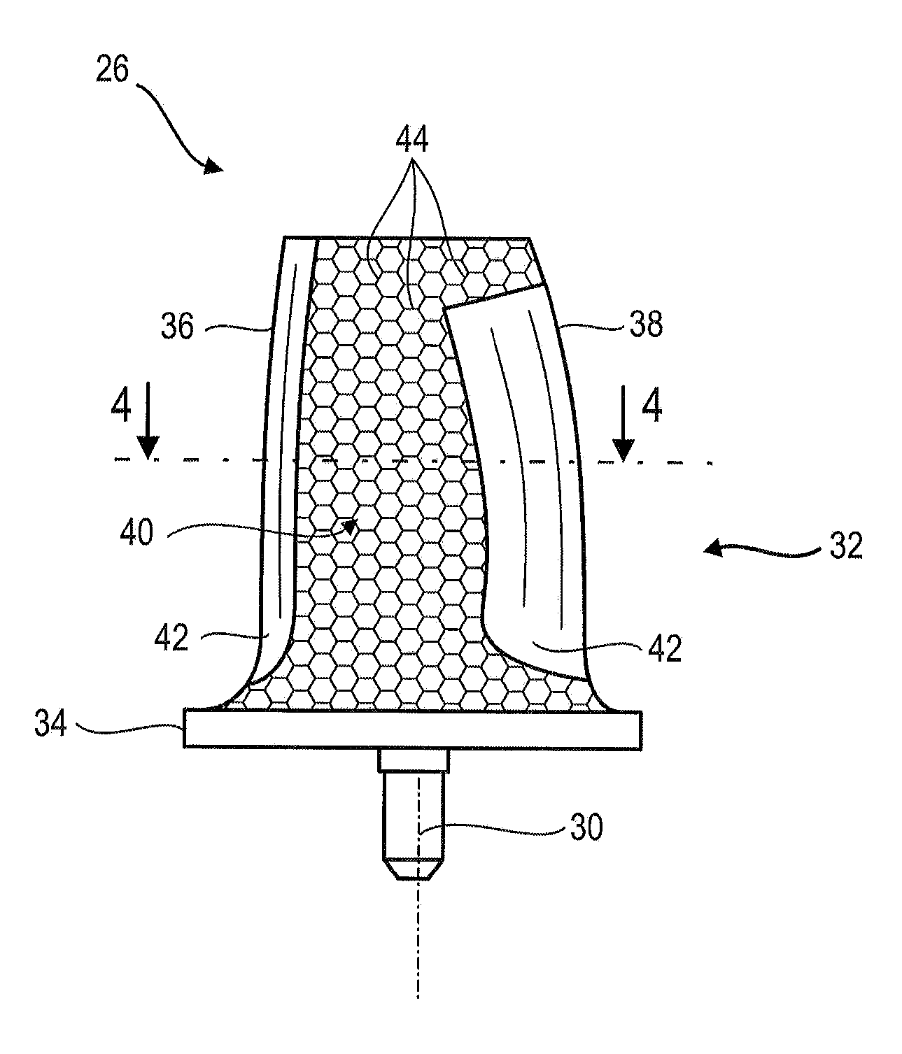
[0083]FIG. 5 outlines a layout of a rod 44 of the reinforcement portion 40 of the blade according to the present application. The orientation of the rods may vary locally.

[0084]The rods 44 are arranged in three non-coplanar directions. The three directions may be inclined relative to each other at different angles. Three directions can be at right angles. The rods 44 then define hexahedrons such as cubes whose edges may be inclined relative to the height of the blade.

[0085]The rods 44 interconnected to each other form connecting nodes 52. Connecting nodes are typically distributed into three sets of planes 54. Each set of planes 54 comprises parallel planes, the sets of planes 54 being inclined with each other. A connecting node 52 may be connected to six other connecting nodes 52. Connecting nodes may be arranged on sets of curved surfaces, e.g. surfaces generally conforming to the pressure side surface or the suction side surface of the blade.

[0086]The rods 44 generally have the s...

second embodiment

[0088]FIG. 6 shows an arrangement of the rods 144 of a portion of the reinforcement 140 of the blade according to the present application. This FIG. 6 uses the numbering of the preceding figures for the same or similar elements, however this numbering is incremented by 100.

[0089]The rods 144 are arranged in four non-coplanar directions, preferably in at least four non-coplanar directions. A connecting node 152 of rods 144 is connected to four other connecting nodes 152 of rods 144 which form a tetrahedron, whose center can be occupied by the common connecting node. The orientation and length of the rods vary within the reinforcement. The four directions define between them different angles (β1, β2, β3, β4, β5, β6). These angles can be equal.

[0090]According to one alternative of the present application, the reinforcing rods can be arranged in six directions, some directions being coplanar. The rods can form pyramids with a triangular base. In this configuration, a same connecting nod...


PUM

PropertyMeasurementUnit
Fractionaaaaaaaaaa
Fractionaaaaaaaaaa
Fractionaaaaaaaaaa

Abstract

The present application relates to a blade of a rectifier of a low pressure compressor of an axial turbomachine. The blade can also be a rotor and/or turbine blade. The blade includes a composite material with a matrix and a reinforcement comprising a mesh with rods. The rods of the reinforcement are connected to each other and are distributed throughout the volume between the pressure side surface and the suction side surface of the blade. The mesh forms a three-dimensional structure extending over the majority of the thickness of the blade between the pressure side surface and the suction side surface and/or the majority of the length of the blade between the leading edge and the trailing edge. The present application also relates to an iterative method for manufacturing a blade composite where the reinforcement is formed by additive layer manufacturing based on titanium powder and then placed in an injection mold.

Description

[0001]This application claims priority under 35 U.S.C. §119 to European Patent Application No. 13181971.6, filed 28 Aug. 2013, titled “Composite Blade Made by Additive Manufacturing,” which is incorporated herein by reference for all purposes.BACKGROUND[0002]1. Field of the Application[0003]The present application relates to a turbomachine composite blade. More particularly, the present application relates to a composite blade with reinforcement and a matrix. The present application also relates to a turbine engine with a blade according to the present application. The present application also relates to a method of manufacturing a composite blade with reinforcement and a matrix.[0004]2. Description of Related Art[0005]An axial turbomachine comprises annular rows of rotor blades for accelerating a flow of air, and annular rows of stator blades which redress or rectify the accelerated flow of air. The blades must be lightweight to reduce the mass of the turbomachine. In particular, t...

Claims


Application Information

Patent Timeline
IPC IPC(8): F01D5/28B28B1/00B29C45/14
CPCF01D5/282B29C45/14631B28B1/001F05D2230/30F05D2300/6032B33Y80/00B29K2079/085B29K2305/00B29K2309/02B29L2031/08B33Y10/00F05D2300/44F05D2300/6033F05D2300/6031F05D2230/31B29C70/70B29D99/0025Y02T50/60F01D5/147
Inventor PEREZ, RAFAEL
Owner TECHSPACE AERO
Why Eureka
Try Eureka