Low-power data acquisition system and sensor interface

a data acquisition system and low-power technology, applied in the field of low-power data acquisition systems and sensor interfaces, can solve the problems of insufficient solution for applications, device access to relatively high power or voltage levels, and insufficient solution for prior art devices

Active Publication Date: 2015-03-05
AVAGO TECH INT SALES PTE LTD
View PDF3 Cites 26 Cited by
  • Summary
  • Abstract
  • Description
  • Claims
  • Application Information

AI Technical Summary

Problems solved by technology

However, there are many deficiencies within such sensor-based systems including the interfacing between sensor devices and other components within the system.
As an example, the interface between a sensor and a processor device can difficult and challenging to design for a number of reasons.
Many prior art devices require access to relatively high power or voltage levels to perform properly.
The prior art...

Method used


Image

  • Low-power data acquisition system and sensor interface
  • Low-power data acquisition system and sensor interface
  • Low-power data acquisition system and sensor interface

Examples


embodiment 101

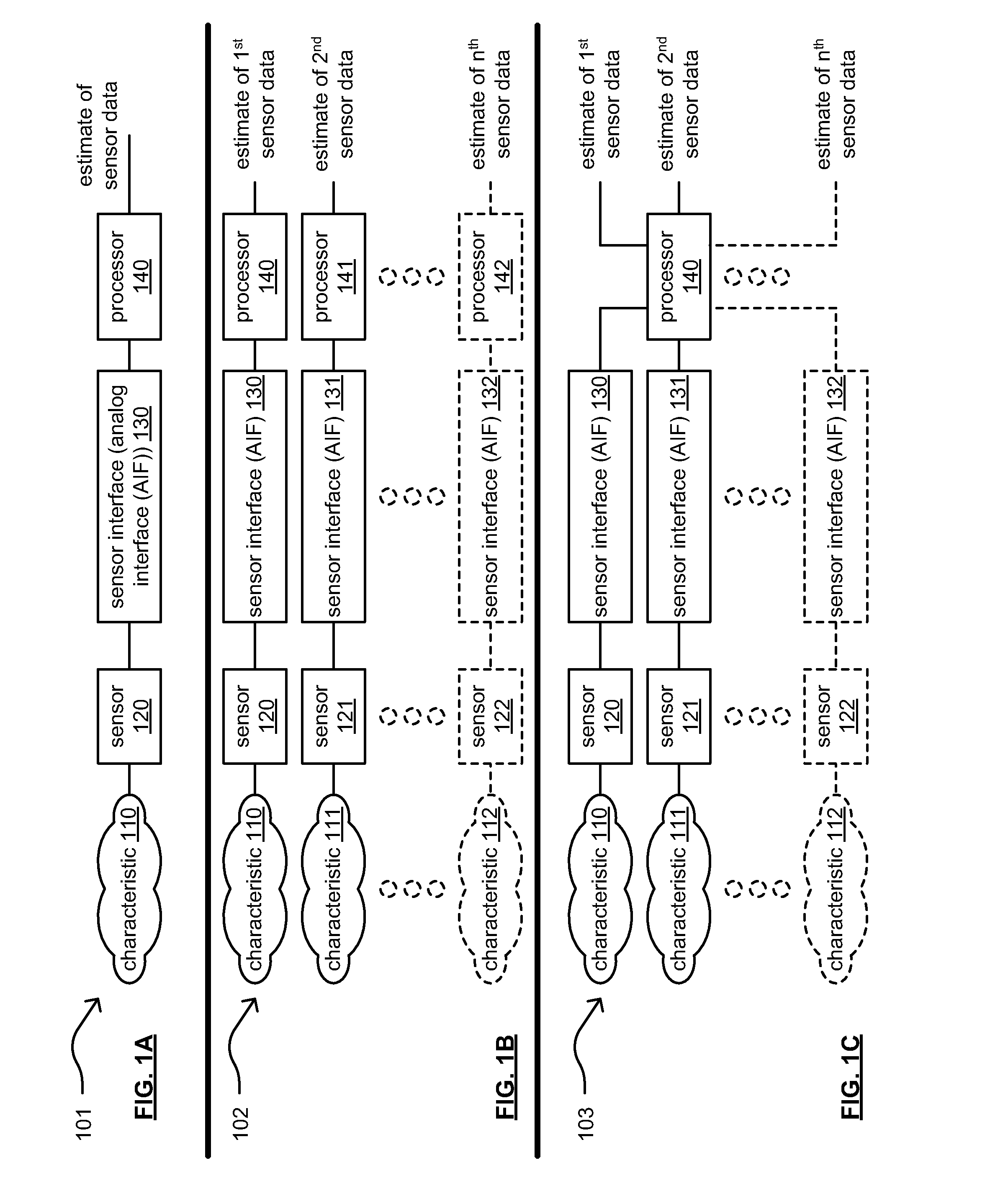
[0021]FIG. 1A is a diagram illustrating an embodiment 101 of one or more communication systems that includes a sensor interface. This disclosure presents various novel solutions for sensor interfaces and other components within sensor-based systems. The various embodiments and examples presented herein may be implemented within a wide variety of applications including those implemented in a general sensing environment. There are many examples of sensing environments and sensor-based systems. Some examples include those sensor-based systems directed towards applications within any one of biomedical, environmental, security, processing, manufacturing, operational, etc. applications. Generally speaking, the various architectures and designs presented in this disclosure may be adapted and applied to any desired sensor-based system. Some examples of environmental characteristics include temperature, humidity, barometric pressure, etc. Some examples of biomedical characteristics include b...

embodiment 102

[0026]FIG. 1B is a diagram illustrating another embodiment 102 of one or more communication systems that includes a sensor interface. In this diagram, a number of characteristics 110, 111, through 112 are monitored or detected by respective sensors 120, 121, through 122. Each respective sensor provides a sensor signal to a corresponding sensor interface. For example, sensor 120 provides a first sensor signal to sensor interface 130, sensor 121 provides a second sensor signal to sensor interface 131, and so on. Each respective sensor interface provides a digital signal to a respective processor. Sensor interface 130 provides a first digital signal to processor 140 that generates an estimate of first sensor data associated with characteristic 110. Sensor interface 131 provides a second digital signal to processor 141 that generates an estimate of second sensor data associated with characteristic 111. Generally speaking any number of characteristics up to characteristic 112, any number...

embodiment 202

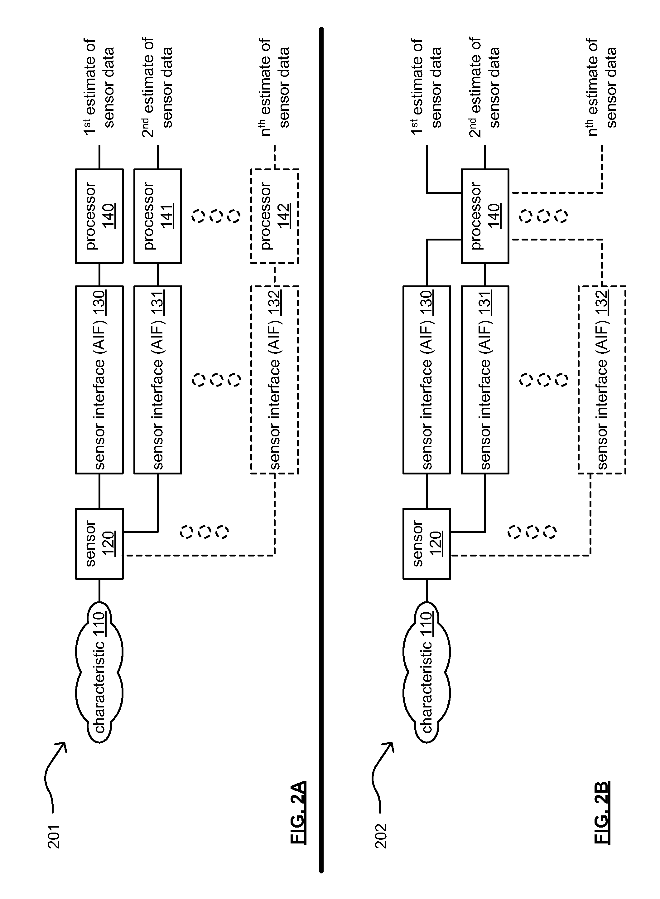
[0029]FIG. 2B is a diagram illustrating another embodiment 202 of one or more communication systems that includes a sensor interface. The embodiment 202 of this diagram is similar to the embodiment 201 of the previous diagram with the exception that a single processor 140 receives the digital signals provided from the sensor interfaces 130-132. In this diagram, a single processor 140 may then differentiate characteristics between the different digital signals provided via different sensor interfaces based on knowledge of the particular architecture and design of the different sensors. If desired, the processor 140 may select among and use different digital signals provided from the different sensor interfaces 130-132 based on any consideration. For example, in certain instances, a digital signal provided by one of the sensor interfaces 130-132 may be preferable over another digital signal provided by another one of the sensor interfaces 130-132. There may be instances in which diffe...


PUM


Abstract

A sensor interface includes on-chip relaxation oscillator circuit and a PLL that operate cooperatively to generate a highly accurate clock signal on-chip using low-power components. A photodiode generates a current signal based on an optical signal that is representative of a sensor signal. An ADC that operates based on the highly accurate clock signal generates a digital signal based on the current signal generated by the photodiode, and a processor processed the digital signal to estimate sensor data within the sensor signal. Examples of characteristics that may be sensed can include environmental characteristics (e.g., temperature, humidity, barometric pressure, etc.) and/or biomedical characteristics (e.g., body temperature, heart rate, respiratory rate, blood pressure, etc.). In desired, an amplifier processes the photodiode-provided current signal before it is provided to the ADC. Also, one or more CDACs that generate feedback currents may be used to reduce noise sensitivity of the sensor interface.

Description

CROSS REFERENCE TO RELATED PATENTS / PATENT APPLICATIONSProvisional Priority Claims[0001]The present U.S. Utility patent application claims priority pursuant to 35 U.S.C. §119(e) to U.S. Provisional Application No. 61 / 872,075, entitled “Low-power data acquisition system and sensor interface,” filed Sep. 30, 2013; and U.S. Provisional Application No. 61 / 872,352, entitled “Low-power data acquisition system and sensor interface,” filed Sep. 30, 2013, both of which are hereby incorporated herein by reference in their entirety and made part of the present U.S. Utility patent application for all purposes.BACKGROUND[0002]1. Technical Field[0003]The present disclosure relates generally to communication systems; and, more particularly, to sensors and sensing functionality within such communication systems.[0004]2. Description of Related Art[0005]Sensor-based systems are implemented in a variety of applications. Examples of such systems include those that include one or more devices to monitor ...

Claims


Application Information

Patent Timeline
IPC IPC(8): H03B5/04G01R19/00G01K1/00G01L7/00A61B5/021H05B33/08A61B5/01A61B5/024A61B5/08G01J1/00G01N33/00H05B44/00
CPCH03B5/04H03B2202/01G01R19/0092G01K1/00G01L7/00G01N33/0004H05B33/089A61B5/01A61B5/024A61B5/0816A61B5/021H03B2200/0044H03B2200/009H03B2200/0092H03B2202/04G01J1/00A61B2562/06H03K3/0231G01J1/44G01K1/02H05B47/28H05B47/24
Inventor BROOKS, TODD LEEJIANG, XICHENGMEHR, IURISTOOPS, DAVID JOSEPHJAYAKUMAR, VINODKIM, MIN GYUZHENG, HUIKU, I-NINGCHANDRASEKHAR, VINAYCHEUNG, YEE LING
Owner AVAGO TECH INT SALES PTE LTD
Why Eureka
Try Eureka