Manufacturing method of package carrier

a manufacturing method and packaging technology, applied in the direction of electrical equipment, semiconductor devices, semiconductor/solid-state device details, etc., can solve the problems of increased temperature of the led package structure, increased thermal expansion difference, and reduced reliability of use, so as to achieve the effect of reducing the thermal expansion difference and increasing the reliability of us

Active Publication Date: 2015-03-12
SUBTRON TECH
View PDF2 Cites 3 Cited by
  • Summary
  • Abstract
  • Description
  • Claims
  • Application Information

AI Technical Summary

Benefits of technology

[0008]The invention provides a manufacturing method of a package carrier for manufacturing the aforementioned package carrier which effectively decreases a thermal expansion difference when the package carrier carries a heating element and increases a using reliability.
[0021]Based on the above, the manufacturing method of the package carrier of the invention uses an insulation substrate with an ideal thermal expansion coefficient as a core. Therefore, when the package carrier is used in the package of a heating element (such as a chip) subsequently, a difference in thermal expansion coefficient between the package carrier and the heating element carried on the package carrier is reduced effectively, which prevents a stress between the heating element and the insulation substrate from increasing because of a too great difference in thermal expansion coefficient therebetween and effectively prevents the peeling and damage of the heating element from happening, thereby enhancing the using reliability of the package carrier.

Problems solved by technology

A LED chip has to be packaged before used, and the LED chip generates a large amount of heat when emitting light.
Therefore, if the heat generated by the LED chip cannot be dissipated and keeps accumulating in the LED package structure, a temperature of the LED package structure would keep rising.
In this way, the LED chip may be overheated, which causes luminance decay and shortens operating life thereof or even causes permanent damage in server cases.
As the integration level of integrated circuits increases, due to the mismatch of thermal expansion coefficient between the LED chip and the package carrier, the phenomena of thermal stress and warpage become more and more severe, and that causes the reliability between the LED chip and the package carrier to decrease.

Method used


Image

  • Manufacturing method of package carrier
  • Manufacturing method of package carrier
  • Manufacturing method of package carrier

Examples


Embodiment Construction

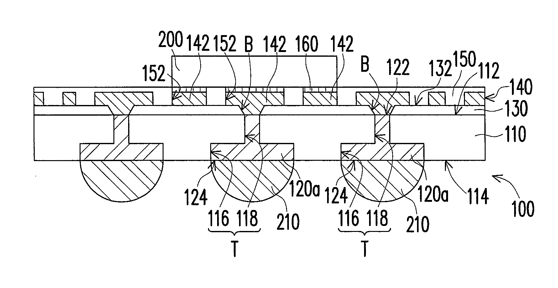
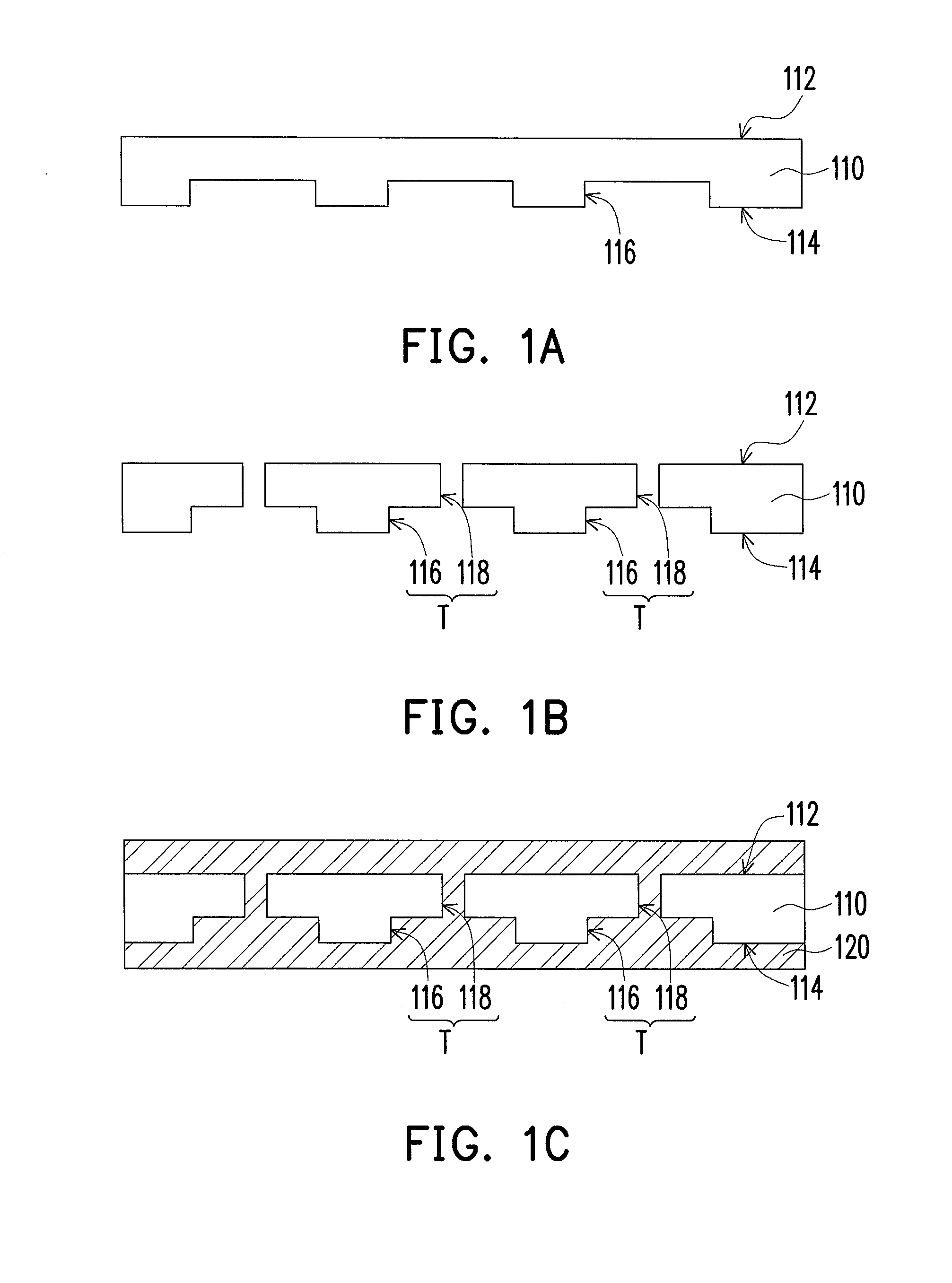
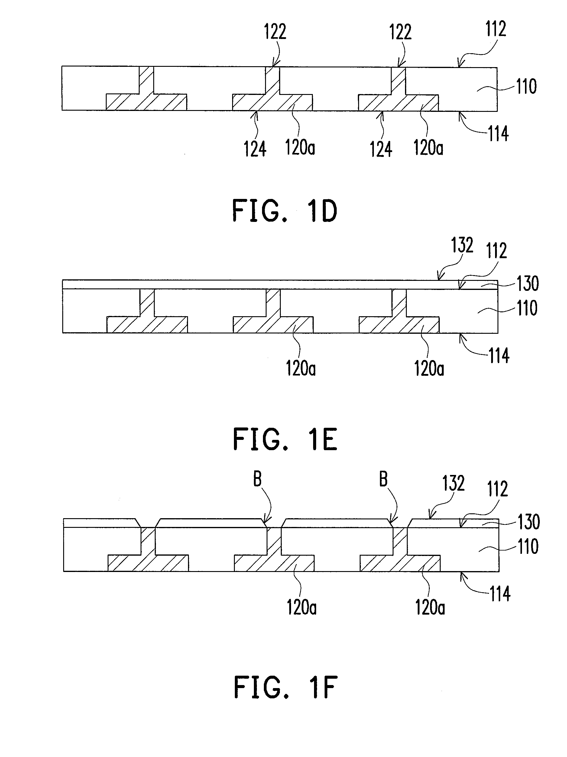
[0026]FIGS. 1A to 1H are schematic cross-sectional views of a manufacturing method of a package carrier according to an embodiment of the invention. According to the manufacturing method of the package carrier of the present embodiment, referring to FIG. 1A, an insulation substrate 110 is provided first. The insulation substrate 110 has an upper surface 112, a lower surface 114 opposite to the upper surface 112 and a plurality of cavities 116, wherein the cavities 116 are located at the lower surface 114 of the insulation substrate 110. Herein, a method of forming the cavities 116 of the insulation substrate 110 is, for example, laser drilling or injection molding. In addition, a material of the insulation substrate 110 is, for example, ABF resin, polymeric materials, silicon fillers or epoxy resin.

[0027]Then, referring to FIG. 1B, through holes 118 passing through the insulation substrate 110 and respectively communicating with the cavities 116 are formed on the upper surface 112 o...


PUM

PropertyMeasurementUnit
conductiveaaaaaaaaaa
contact densityaaaaaaaaaa
temperatureaaaaaaaaaa

Abstract

A manufacturing method of a package carrier is provided. An insulation substrate having an upper surface, a lower surface, plural cavities located at the lower surface and plural through holes passing through the insulation substrate and respectively communicating with the cavities is provided. Plural vias is defined by the cavities and the through holes. A conductive material filling up the vias is formed to define plural conductive posts. An insulation layer having a top surface and plural blind vias extending from the top surface to the conductive posts is formed on the upper surface. A patterned circuit layer filling up the blind vias, being connected to the conductive posts and exposing a portion of the top surface is formed on the top surface. A solder mask layer is formed on the patterned circuit layer and has plural openings exposing a portion of the patterned circuit layer to define plural pads.

Description

CROSS-REFERENCE TO RELATED APPLICATION[0001]This application is a divisional application of and claims the priority benefit of U.S. application Ser. No. 13 / 615,698, filed on Sep. 14, 2012, now pending. The prior application Ser. No. 13 / 615,698 claims the priority benefit of Taiwan application serial no. 101128619, filed on Aug. 8, 2012. The entirety of each of the above-mentioned patent applications is hereby incorporated by reference herein and made a part of this specification.BACKGROUND[0002]1. Field of the Invention[0003]The invention relates to a manufacturing method of a package structure, and more particularly, to a manufacturing method of a package carrier.[0004]2. Description of Related Art[0005]The purpose of chip package is to protect exposed chips, to reduce contact density in a chip, and to provide good thermal dissipation for chips. A leadframe serving as a carrier of a chip is usually employed in a conventional wire bonding technique. As contact density in a chip grad...

Claims


Application Information

Patent Timeline
Patent Type & Authority Applications(United States)
IPC IPC(8): H05K3/42H01L21/48
CPCH01L21/486H05K3/42H01L23/49827H01L33/44H01L33/486H01L33/62H01L33/642H01L2924/15311H01L21/447H01L2224/16227H01L2224/16225H01L2924/00014Y10T29/49165H01L2224/0401
Inventor SUN, SHIH-HAO
Owner SUBTRON TECH
Why Eureka
Try Eureka