Composite body

A technology of assembly and intermediate layer, which is used in electrolytic components, transportation and packaging, electrodes, etc., can solve the problems of reduced bonding strength and different thermal expansion coefficients between cermet components and metal components, and achieve the effect of high bonding strength.

Active Publication Date: 2018-01-02
TDK CORPARATION
View PDF7 Cites 2 Cited by
  • Summary
  • Abstract
  • Description
  • Claims
  • Application Information

AI Technical Summary

Problems solved by technology

However, when a cermet member is used as a substitute material for the ferrite member of the electrode, the thermal expansion coefficients of the cermet member and the metal member are greatly different, and therefore the bonding strength between the cermet member and the metal member decreases.

Method used


Image

  • Composite body
  • Composite body
  • Composite body

Examples


Embodiment 1~45 and comparative example 1~24

[0211] Combine commercially available NiO powder and Fe 2 O 3 Powder with NiO and Fe 2 O 3 The molar ratio becomes 70:30, and the ball mill is used for mixing. The mixed powder obtained by mixing was maintained in the atmosphere at a temperature of 1000° C. for 3 hours to perform calcining. The calcined powder obtained by calcination was pulverized with a ball mill to prepare ferrite oxide powder.

[0212] The obtained ferrite oxide powder and metal powder are mixed. Here, as the metal powder, Ni powder, mixed powder of Ni powder and Cu powder, mixed powder of Ni powder and Ag powder, and mixed powder of Ni powder, Cu powder and Ag powder are prepared. Regarding the mixed powder of Ni powder and Cu powder, the mass ratio of Ni and Cu satisfies the mixing ratio of 45

Embodiment 50~75

[0249] In Experimental Example 2, different from Experimental Example 1, the NiO powder and Fe 2 O 3 The mixing ratio of the powder is set to NiO and Fe 2 O 3 The molar ratio of is 50:50. In addition, the joining time has also changed. Furthermore, intermediate members of the materials shown in Table 2 were prepared (only the first intermediate member was used in Example 50, the first intermediate member and the second intermediate member were used in Examples 51 to 69, and the first intermediate member was excluded in Examples 70 to 75. An intermediate member, the second intermediate member is also a third intermediate member). The thickness of each intermediate member was set to 0.02 cm.

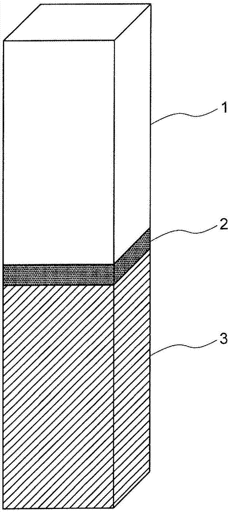
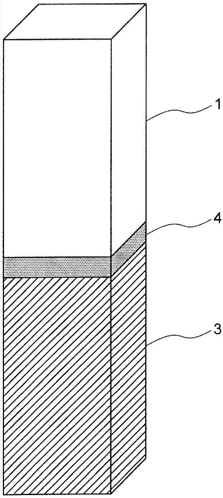
[0250] Furthermore, when the third intermediate member was not used (Examples 51 to 69), the first intermediate member was placed on the cermet member, the second intermediate member was placed on the first intermediate member, and the metal member was placed on the On the second intermedia...

Embodiment 80~92

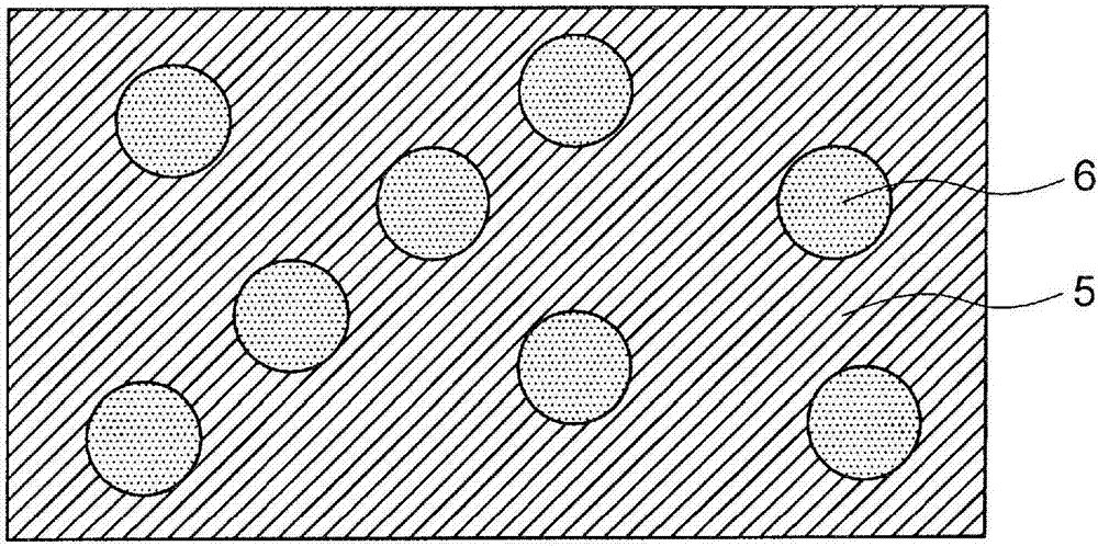
[0260] In Experimental Example 3, as in Experimental Example 2, the NiO powder and Fe 2 O 3 The mixing ratio of the powder is set to NiO and Fe 2 O 3 The molar ratio of is 50:50. Furthermore, as the intermediate member, a hybrid molded body produced by the production method shown below was used. Except for the aforementioned points and certain conditions described in Table 5, in the same manner as in Example 50 of Experimental Example 2, Examples 81 to 92 shown in Table 5 were obtained. Furthermore, various characteristics shown in Table 5 and Table 6 were measured. In all the examples, no cracks occurred, and the void ratio on the intermediate member was less than 5%.


PUM

PropertyMeasurementUnit
melting pointaaaaaaaaaa
thicknessaaaaaaaaaa
thicknessaaaaaaaaaa

Abstract

The present invention addresses the problem of providing a composite body of a metal member and a cermet member, which exhibits sufficient joining strength. The solution is a composite body having a cermet member, a metal member and an intermediate member. The cermet member includes a cermet oxide phase and a cermet metal phase. The cermet oxide phase contains a Ni-containing oxide or an Fe-containing oxide. The cermet metal phase contains Ni. The intermediate layer contains Cu. The mass proportions of Cu in the cermet metal phase at points which are spaced apart by 10, 50, 100 and 1000 [mu]mfrom the interface between the cermet member and the intermediate layer to the cermet member side are denoted by C10, C50, C100 and C1000 (mass%). When the mass proportions of Cu in the cermet oxide phase at points which are spaced apart by 10 and 100 [mu]m from the interface to the cermet member side are denoted by M10 and M100 (mass%), C10 > C50 > C100 > C1000, and 5 > M10-M100 > -5.

Description

Technical field [0001] The present invention relates to an assembly of an intermediate layer sandwiching a cermet member and a metal member. Background technique [0002] In the refining of rare earth metals, chloride electrolysis or oxide electrolysis has been used. In the chloride electrolysis method, a large amount of chlorine gas is generated. In contrast, most of the generated gas in the oxide electrolysis method using oxides is carbon monoxide (CO) or carbon dioxide (CO 2 ). The generation of carbon monoxide and carbon dioxide is more environmentally preferable than the generation of chlorine (Non-Patent Document 1). [0003] In recent years, from the viewpoint of global warming, we have further sought to reduce CO and CO 2 Gas, seek to not produce CO, CO 2 Inert anode for gas. Therefore, from the viewpoint of improving the electrical conductivity of ceramics, a cermet (Cermet) material in which metal is added to ceramics has been developed (Patent Document 1). However, e...

Claims


Application Information

Patent Timeline
Patent Type & Authority Applications(China)
IPC IPC(8): B22F7/08
CPCB22F5/00B22F7/02B22F7/064C22C29/12B22F2207/01B22F2998/10B22F2999/00C25C7/025B32B2250/05B32B2250/03B32B2250/04B32B2307/50B32B2307/732B32B15/16B32B2264/12B32B15/18B32B2260/025B32B5/30B32B2264/105B32B7/023B32B2307/30B32B2307/714B32B7/04B32B2255/205B32B2260/046B32B5/16C22C1/0425C22C1/0433C22C1/05B22F1/10B22F3/02B22F3/10B22F3/162B22F3/16B22F2207/03B32B15/20B32B2311/12B32B2311/22B32B2315/02C22C29/00B32B15/043B32B18/00
Inventor 中泽辽马吉留和宏
Owner TDK CORPARATION
Why Eureka
Try Eureka