Inductor and switching circuit including the same

a switching circuit and inductor technology, applied in the direction of transformer/inductance, magnetic core, core/yokes, etc., can solve the problems of deteriorating current waveform, increasing the volume of the inductor, and increasing the cost of manufacturing an inductor, so as to reduce the loss of eddy current in the coil, the effect of lowering costs

Inactive Publication Date: 2015-03-12
DELTA ELECTRONICS (SHANGHAI) CO LTD
View PDF4 Cites 12 Cited by
  • Summary
  • Abstract
  • Description
  • Claims
  • Application Information

AI Technical Summary

Benefits of technology

[0008]One object of the present disclosure is to provide an inductor which may provide a non-linear inductance, may improve non-linear inductance graphs by adjusting a thickness and a cross sectional area of a material having a high permeability and a low saturation magnetic flux density, and meanwhile may lower costs and reduce eddy-current loss in coils.
[0025]As compared with conventional technologies, the inductor and the switching circuit proposed by the present disclosure are capable of providing a non-linear inductance and meanwhile lowering costs and reducing eddy-current loss in coils.

Problems solved by technology

However, if a large inductance is maintained from a light load current to a rated current, costs for manufacturing an inductor will rise, and a volume of the inductor will be increased.
However, such inductor has defects that once the magnetic core in the step portion is saturated, the inductance will decline sharply, even lower than the inductance of a common inductor under a certain current, which will on the contrary result in deteriorated current waveforms, and that the manufacture process of such inductor is complicated.
Such inductor has a defect that a relatively large amount of the material having a low permeability of the magnetic core is needed during manufacturing, which results in additional costs.

Method used


Image

  • Inductor and switching circuit including the same
  • Inductor and switching circuit including the same
  • Inductor and switching circuit including the same

Examples


first embodiment

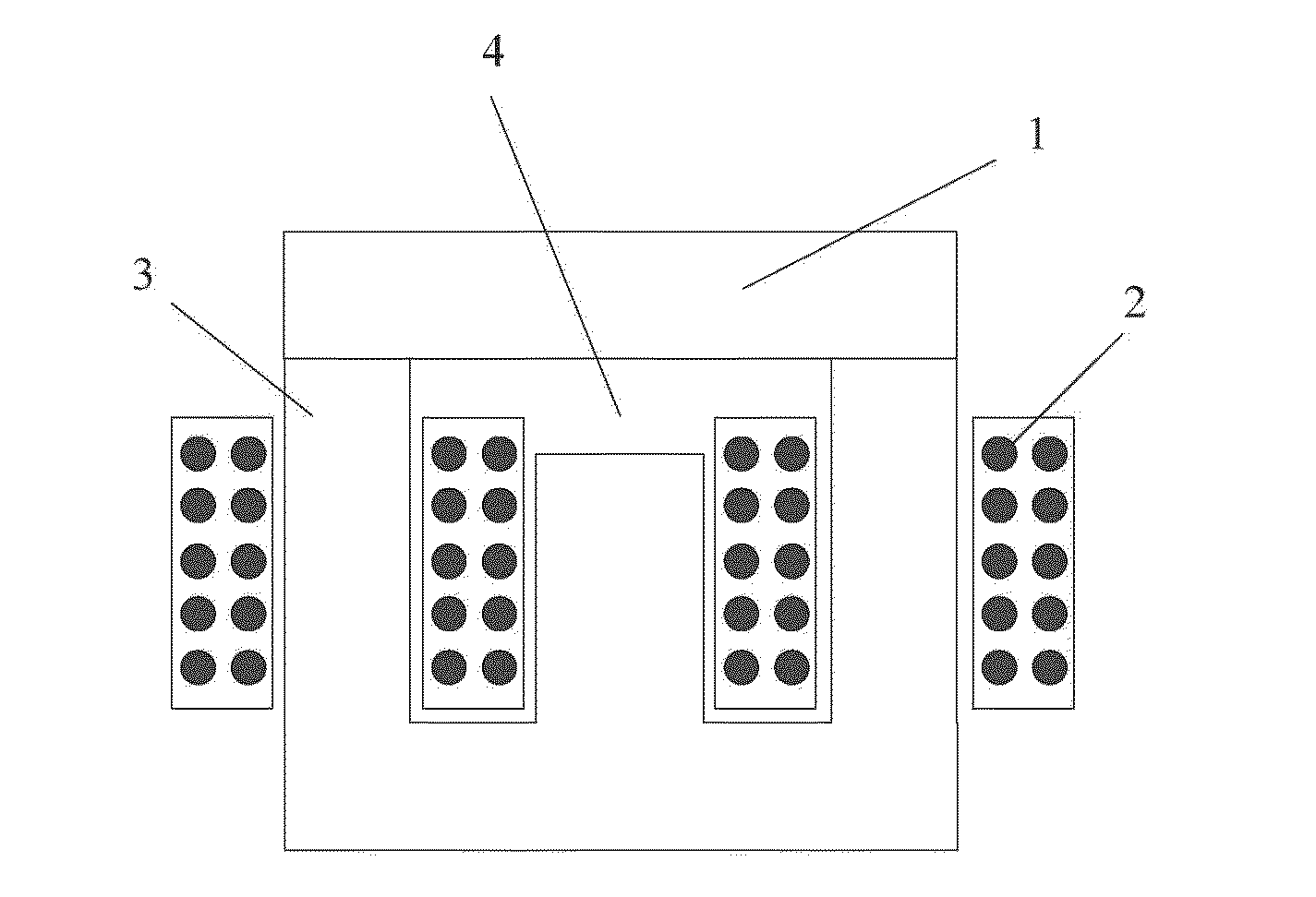
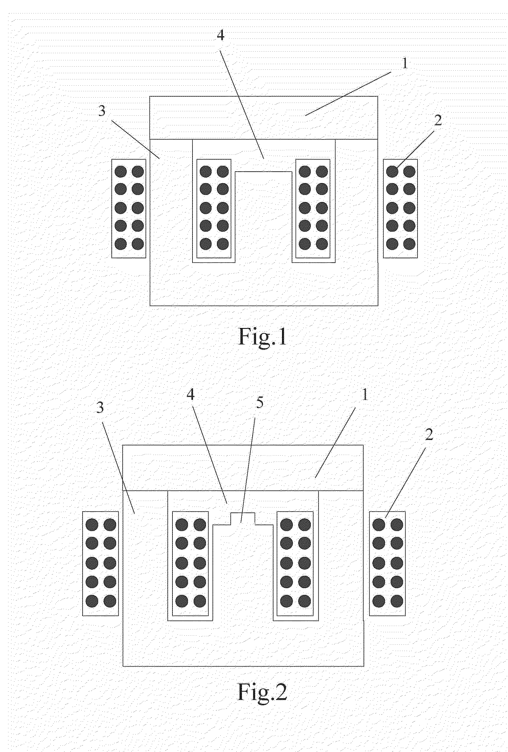
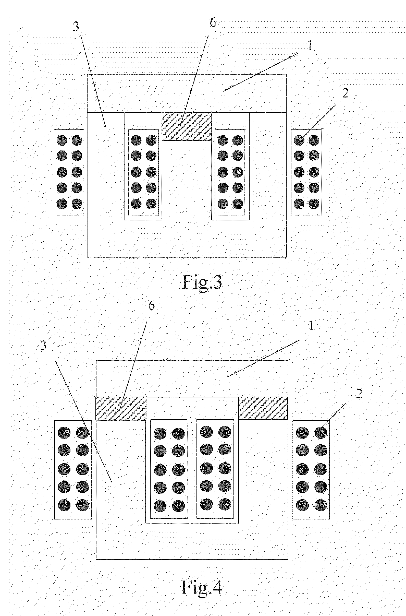
[0040]The present embodiment provides an inductor, a schematic side view of which is shown in FIG. 5. The inductor has a UI structure and includes a magnetic core structure composed of a yoke 101 and a limb 103. The yoke 101 and the limb 103 form a closed magnetic path. The limb is a portion of the magnetic core wounded by a winding, and the yoke is a portion of the magnetic core not wounded by the winding. This also applies to following embodiments.

[0041]A winding 102 is provided as wounded on the limb 103, and an insulating plate 104 close to the yoke portion and a flat magnetic core unit 105 close to the limb 103 portion are included between the limb 103 and the yoke 101.

[0042]A material of the limb 103 and the yoke 101 is a material having a high permeability and a high saturation magnetic flux density (for example, a silicon steel sheet, amorphous or nanocrystalline and so on) which have a relative permeability greater than or equal to 500. A material of the flat magnetic core ...

second embodiment

[0069]The present embodiment provides another inductor structure, a schematic side view of which is shown in FIG. 10.

[0070]The inductor has a UI type structure and includes a magnetic core structure composed of a yoke 201 and a limb 203. The yoke 201 and the limb 203 form a closed magnetic path. A winding 202 of coils is provided as wound on the limb 203, an insulating plate 204 close to the yoke 101 portion and a flat magnetic core unit 205 close to the limb 203 portion are included between the limb 203 and the yoke 201.

[0071]A material of the magnetic core composed of the limb 203 and the yoke 201 is a material having a high permeability and a high saturation magnetic flux density (for example, a silicon steel sheet, amorphous or nanocrystalline and so on) which have a relative permeability greater than or equal to 500. A material of the flat magnetic core unit 205 is a material having a high permeability and a low saturation magnetic flux density (for example, manganese zinc ferr...

third embodiment

[0079]The present embodiment provides another inductor structure, a schematic side view of which is shown in FIG. 13.

[0080]The inductor has a three-phase five-limb structure and includes a magnetic core structure composed of at least one yoke and at least one limb. The at least one yoke and the at least one limb form a closed magnetic path. The at least one yoke includes an upper yoke 301, a lower yoke 301-1 and a side yoke 301-2.

[0081]A winding 302 of coils is provided as wound on the limb 303, and an insulating plate 304 close to the yoke portion and a flat magnetic core unit 305 close to the limb 303 portion are included between the limb 303 and the upper and lower yokes 301, 301-1. The magnetic core structure in the present embodiment includes three limbs, and the limb 303 is one of the three. The flat magnetic core unit 305 is provided between an upper end of each limb and the upper yoke, and the flat magnetic core unit 305 is provided between a lower end of each limb and the l...


PUM

PropertyMeasurementUnit
saturation magnetic flux densityaaaaaaaaaa
thicknessaaaaaaaaaa

Abstract

The present disclosure provides an inductor and a switching circuit including the inductor. The inductor at least includes a winding, and a magnetic core which includes one or more limbs and further includes one or more yokes adapted to form a closed magnetic path, the winding being wounded on the limbs. A gap is provided between at least one end of at least one of the limbs and at least one of the yokes, a flat magnetic core unit is provided in the gap, the flat magnetic core unit is formed of a material having a high permeability and a low saturation magnetic flux density, the limbs and yokes are formed of a material having high permeability and high saturation magnetic flux density, and the saturation magnetic flux density of the material of the flat magnetic core unit is lower than that of the material of the limbs and yokes.

Description

CROSS-REFERENCE TO RELATED APPLICATIONS[0001]This application claims priority under 35 U.S.C. §119 to Chinese Patent Application No. 201310407672.X, filed on Sep. 9, 2013, the entire contents of which are incorporated herein by reference.TECHNICAL FIELD[0002]The present disclosure relates to an inductor and a switching circuit including the inductor.BACKGROUND[0003]At present, different kinds of inductors are widely applied in various circuits, for example, inductors used at a Direct Current (DC) side and an Alternating Current (AC) side in rectifying input circuits and DC inverter circuits, inductors used in switching conversion circuits such as DC conversion circuits (for example, Buck circuits and Boost circuits and so on), etc. Usually, when an inductor is used, it is usually required to maintain inductance as stable as possible within a rated range, at least not lower than minimum inductance requirements. It is found in actual use that an increased inductance may better suppres...

Claims


Application Information

Patent Timeline
Patent Type & Authority Applications(United States)
IPC IPC(8): H01F27/24H02M1/14
CPCH01F27/24H02M2001/0048H02M1/14H01F38/023H01F2003/106
Inventor WANG, ZHAOHUICHU, JIANGHUANG, ZHI
Owner DELTA ELECTRONICS (SHANGHAI) CO LTD
Why Eureka
Try Eureka