Single magnet fluid densitometer

a single magnet, densitometer technology, applied in instruments, surveying, borehole/well accessories, etc., can solve the problems of interfering between the two components, difficulty in accurately recognizing the vibratory response of the flow tube,

Active Publication Date: 2015-03-12
HALLIBURTON ENERGY SERVICES INC
View PDF4 Cites 17 Cited by
  • Summary
  • Abstract
  • Description
  • Claims
  • Application Information

AI Technical Summary

Problems solved by technology

However, due to the limited space in downhole applications, in most of the densitometers described above, the transmitter or driver is often located in close proximity to the receiver and may ...

Method used


Image

  • Single magnet fluid densitometer
  • Single magnet fluid densitometer
  • Single magnet fluid densitometer

Examples


Embodiment Construction

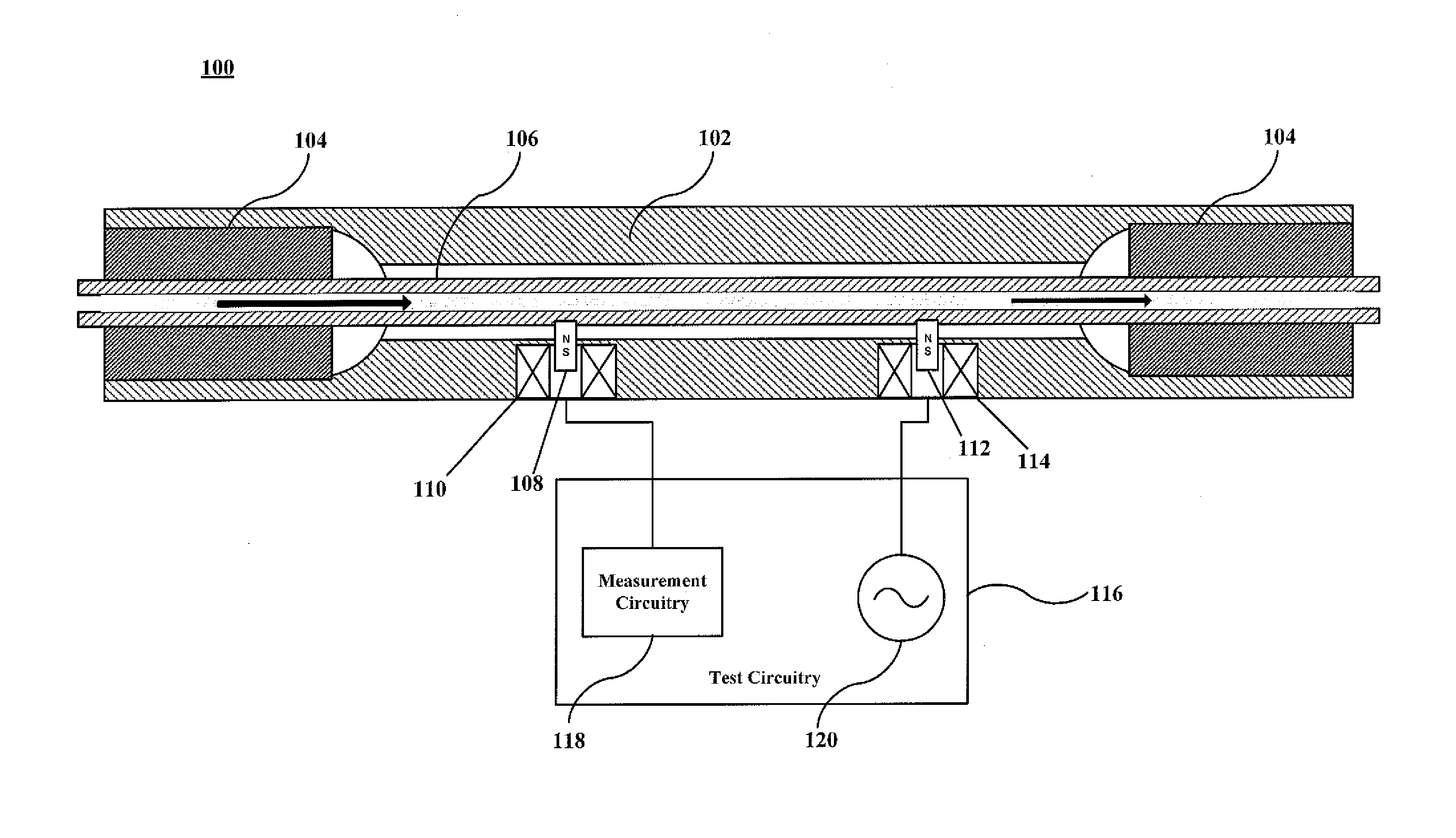
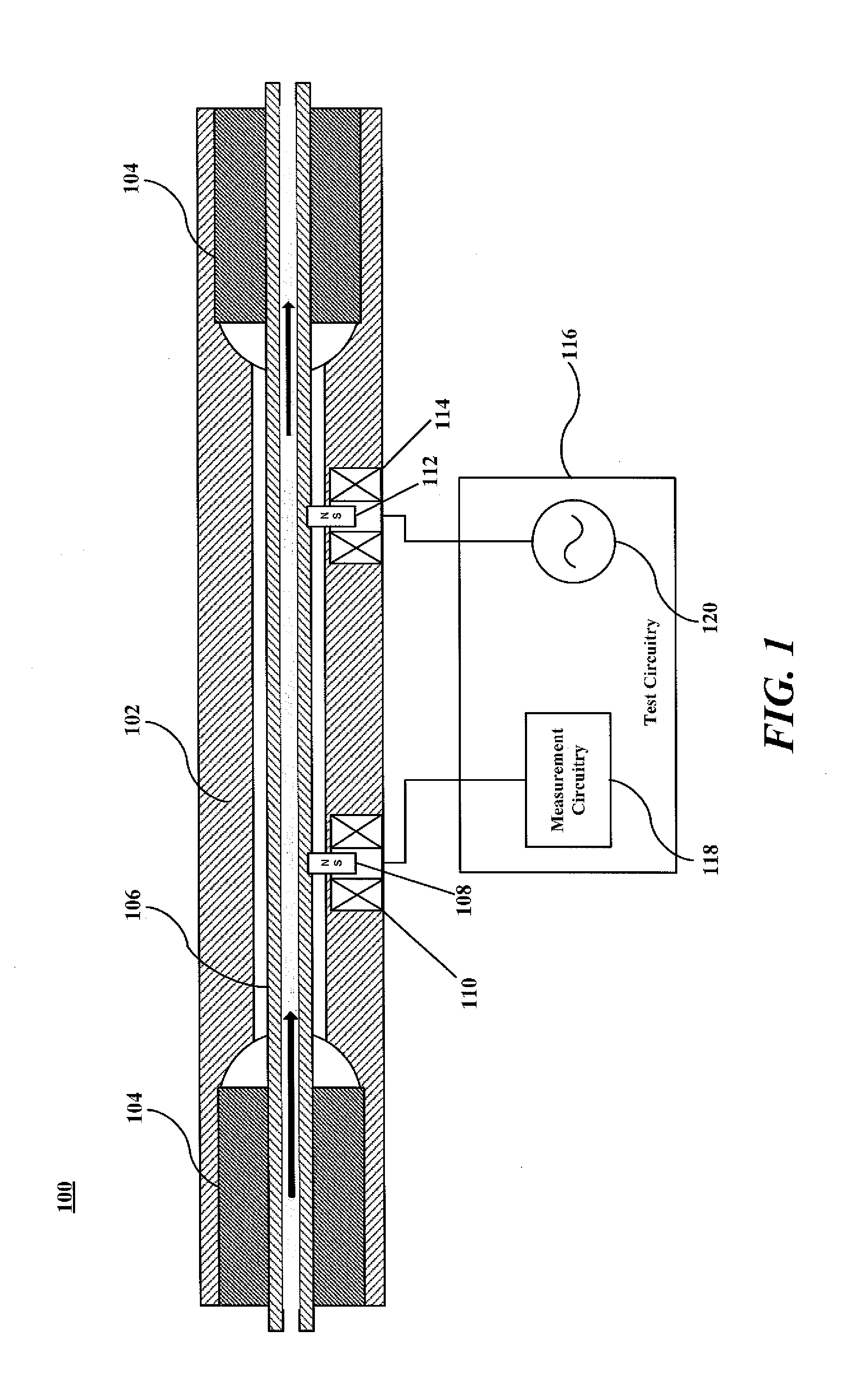
[0024]FIG. 1 is a device for measuring a density of a fluid. As shown in FIG. 1, device 100 includes a rigid housing 102, two bulkheads 104, a single flow tube 106, a first magnet 108 and a first coil 110 wound around first magnet 108, a second magnet 112 and a second coil 114 wound around second magnet 112, and test circuitry 116 which includes measurement circuitry 118 and current source 120. The rigid housing 102 surrounds and protects a volume through which flow tube 106 passes and reduces the response to vibrations not associated with particular vibratory modes of flow tube 106. Bulkheads 104 seal the volume and secure flow tube 106 within that volume. The volume preferably contains air, a vacuum or a relatively inert gas such as nitrogen or argon. If gasses are used, then they are preferably at atmospheric pressure when the device is at room temperature.

[0025]Rigid housing 102, bulkheads 104, and flow tube 106 are preferably made from material in a configuration that can withs...


PUM


Abstract

An instrument for determining fluid properties is provided. The instrument (300) includes a tube (304) receiving the fluid, a single magnet (302) attached to the tube, and a single coil (306) wound around the single magnet. The single coil is coupled to a pulse current source (312) and receives a pulse current that creates a magnetic field in the single coil, the created magnetic field interacting with the single magnet to drive the tube to vibrate. The instrument further includes a detector (306) coupled to the tube, wherein the detector is coupled to measurement circuitry (310) and detects properties of the tube as it vibrates, and the measurement circuitry determines the fluid properties based on the detected properties. The instrument also includes a housing (314) enclosing the tube, the single magnet, and the single coil wound around the single magnet.

Description

BACKGROUND[0001]1. Technical Field[0002]Embodiments disclosed herein generally relate to the measurement of fluid properties. In particular, the disclosed embodiments are related to determining a density of a fluid using a single magnet fluid densitometer.[0003]2. Description of Related Art[0004]There are many instances in industrial processes and controls for handling flowing fluids where the density of the moving fluid has to be determined accurately. One particular application is in the identification of reservoir fluids flowing in a well such as in a pumpout wireline formation tester (PWFT) or logging while drilling formation tester (LWDFT) used to collect reservoir fluid samples in a well drilled for hydrocarbon exploration. The in-situ determination of fluid density under reservoir conditions is of vital importance in formation evaluation. Water often co-exists with gaseous hydrocarbons and crude oil in some common geologic formations. As such, a mixture of water, gaseous hydr...

Claims


Application Information

Patent Timeline
IPC IPC(8): G01N27/74E21B49/08
CPCG01N27/74E21B2049/085E21B49/08E21B47/06E21B49/00G01N9/002G01N11/16G01N33/2823G01N2009/006E21B47/113E21B49/0875
Inventor GAO, LIPELLETIER, MICHAEL T.PROETT, MARK A.
Owner HALLIBURTON ENERGY SERVICES INC
Why Eureka
Try Eureka