Inkjet printer and printing method

a printing method and printer technology, applied in the direction of printing, other printing apparatus, etc., can solve the problems of deterioration of image, unsatisfactory, uneven density, etc., and achieve the effect of reducing the density of the third pixel, reducing the density of the halftone dots printed by the third pixel, and suppressing the unevenness of density

Active Publication Date: 2015-03-12
SEIKO EPSON CORP
View PDF3 Cites 3 Cited by
  • Summary
  • Abstract
  • Description
  • Claims
  • Application Information

AI Technical Summary

Benefits of technology

[0014]When there exists a nozzle that exhibits defective ejection of the ink, a dot omission occurs. First, a position of the first nozzle that exhibits defective ejection of the ink is specified by the nozzle position specifying section. Next, the print control section controls to increase the density of the second pixels which are positioned adjacent to the first pixels to be printed by the first nozzle that was specified. Therefore, the halftone dots printed by the second pixels, in which the density was increased, overlap to a portion where the dot omission occurs so that it makes the dot omission less noticeable.
[0015]On the other hand, it may presume that the density unevenness occurs due to the overlapping of the halftone dots in response to the second pixels and the vicinity of the halftone dots when the printing is performed by the second pixels in which the density was increased. Therefore, the density for the third pixels, which are positioned adjacent to the second pixels except the first pixels, is reduced. Therefore, the density in the halftone dots printed by the third pixels is reduced so that the density unevenness can be suppressed.

Problems solved by technology

When the positions of the dots are changed, the density unevenness occurs due to the overlapping of the dots each other.
When the density unevenness occurs, the deterioration of an image occurs so that it is not desirable.
On the other hand, it may presume that the density unevenness occurs due to the overlapping of the halftone dots in response to the second pixels and the vicinity of the halftone dots when the printing is performed by the second pixels in which the density was increased.

Method used


Image

  • Inkjet printer and printing method
  • Inkjet printer and printing method
  • Inkjet printer and printing method

Examples


first embodiment

1. FIRST EMBODIMENT

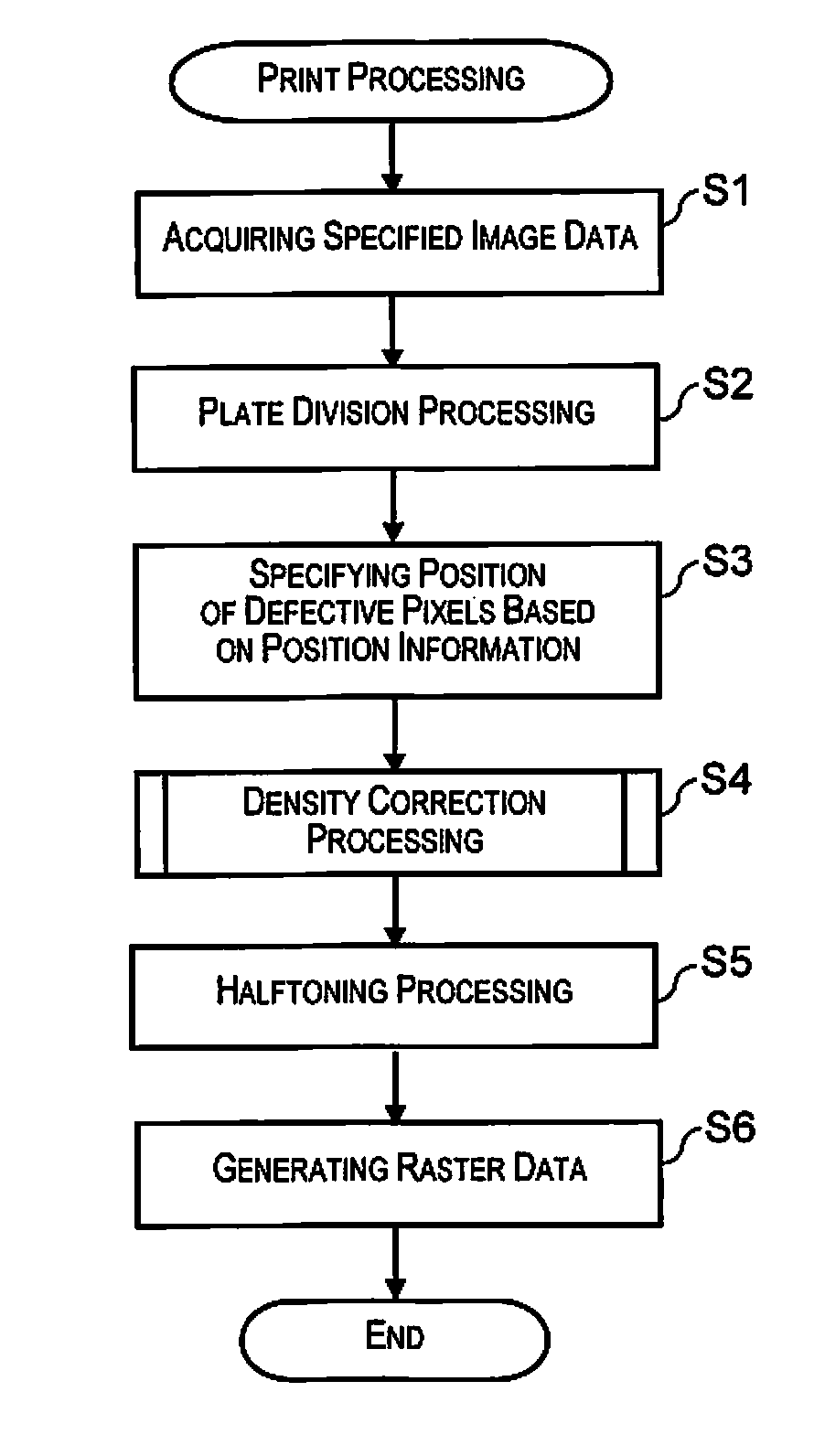
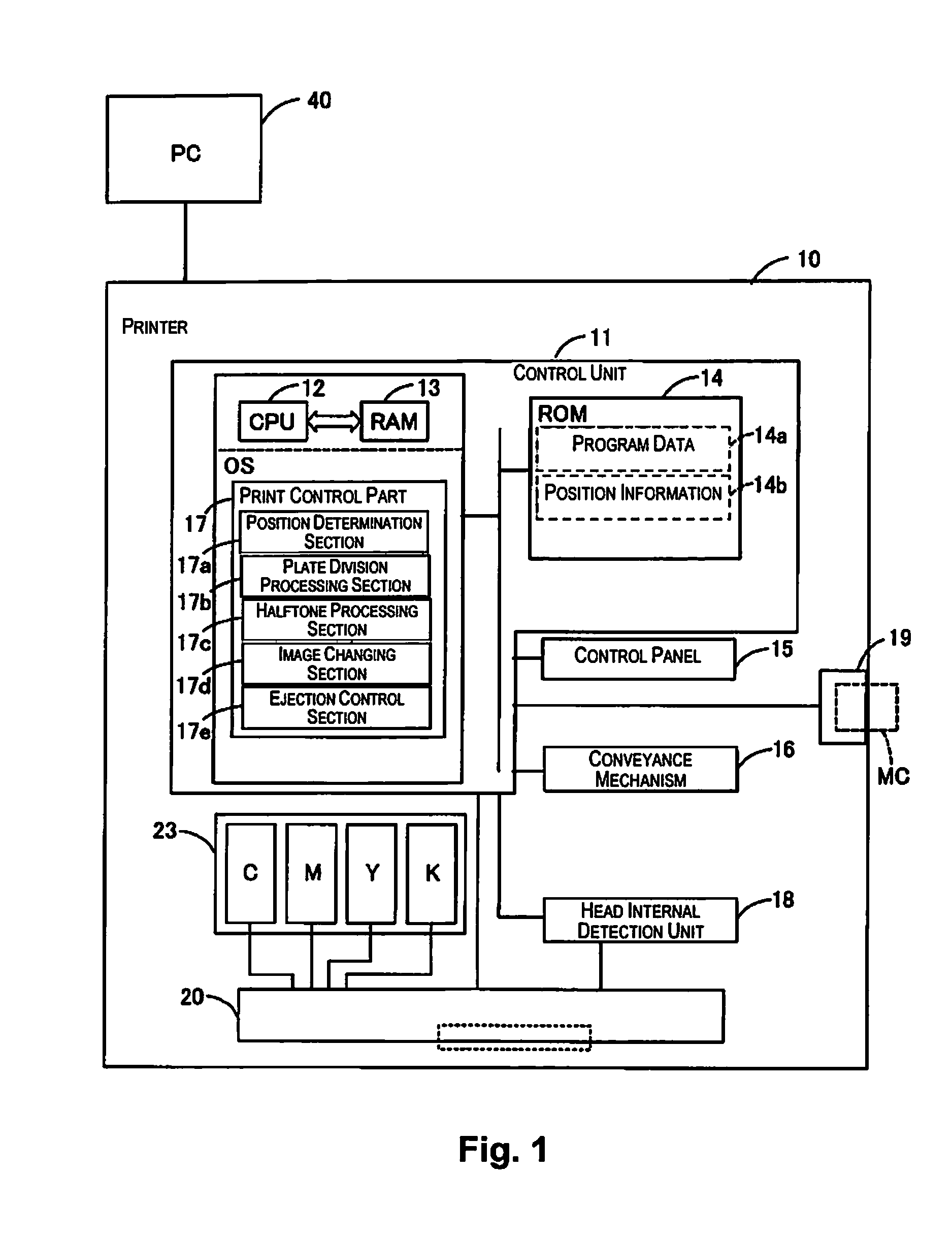
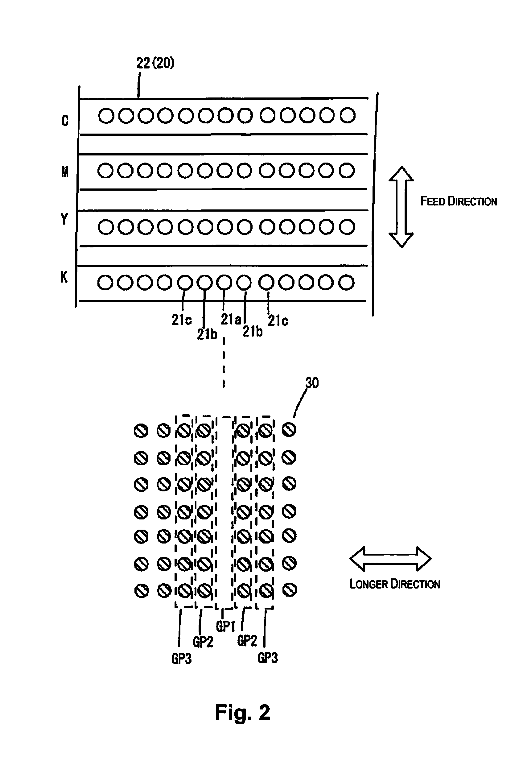
[0044]FIG. 1 schematically shows a hardware configuration and a software configuration according to the present embodiment. FIG. 2 exemplifies a part of each nozzle array in each of CMYK in an ejecting hole face 22 (surface that openings of a nozzle 21 are formed) of a print head 20, and dots on a print substrate printed by the nozzle arrays.

[0045]In FIG. 1, a PC (personal computer) 40 and a printer 10 are shown. The printer 10 corresponds to an inkjet printer. A system including the PC 40 and the printer 10 may be counted as a printing device or an inkjet printing. The printer 10 is provided with a control unit 11 to control a print processing. In the control unit 11, a CPU 12 executes a firmware to control the own device by developing program data 14a, which is stored in a ROM 14, etc., in a RAM 13 and performing operation in accordance with the program data 14a under the OS. The firmware is a program to execute functions of a print control section 17, etc. by t...

second embodiment

2. SECOND EMBODIMENT

[0126]Up to here, it was explained to presume that the printer 10 is provided with the print head 20 as a head for line-type printer. However, the printer 10 is provided with the print head 20 being movable in the scanning axis direction, which is defined in a direction intersecting with the aforementioned feed direction, and that is, it may be a serial printer.

[0127]FIG. 13 is a diagram showing the print head 20 as a head for serial printer.

[0128]In the print head 20, a nozzle array of each color of C, M, Y, K is provided with a plurality of nozzles 23 that is respectively arranged in the feed direction. Therefore, in the second embodiment, the fourth nozzles 23b, which are positioned adjacent to the defective nozzle 23a, are positioned adjacent to the defective nozzle 23a in the feed direction. Also, the fifth nozzles 23c, which are adjacent to the fourth nozzles 23b, are positioned in an opposite side of the defective nozzle 23a with respect to the fourth nozz...

modified example 1

[0130]The position information that the position determination section 17a acquires is not limited to the information supplied from the head internal detection unit 18. For example, a position of a nozzle, in which the defect ejection occurs, may be inputted as the position information by controlling the control panel 15 by the user. In this case, the user controls the printer 10 to print a solid image of each color of, for example, C, M, Y, K. The user observes the solid image and determines a pixel line in which the dot omission occurs. Based on the pixel line that was determined, the user controls the control panel 15 to input the position of the defective nozzle as the position information to the printer 10 so that it is possible that the printer 10 determines the position of the defective pixels P1.

[0131]With such configuration, even though the printer 10 is not provided with the head internal detection unit 18, the present invention can be applied.

[0132]Further, even though it...


PUM


Abstract

An inkjet printer includes a print head, a nozzle position and a print control section. The print head includes a plurality of nozzles to eject ink. The nozzle position specifying section is configured to specify a position of a first nozzle of the plurality of nozzles that exhibits defective ejection of the ink. The print control section is configured to eject the ink from the plurality of nozzles based on image data. The print control section is configured to determine a density of second pixels, which are positioned adjacent to first pixels to be printed by the first nozzle that was specified, and a density of third pixels, which are positioned adjacent to the second pixels except the first pixels, based on the image data, and to correct to increase the density of the second pixels and to reduce the density of the third pixels.

Description

CROSS-REFERENCE TO RELATED APPLICATIONS[0001]This application claims priority to Japanese Patent Application No. 2013-188986 filed on Sep. 12, 2013. The entire disclosure of Japanese Patent Application No. 2013-188986 is hereby incorporated herein by reference.BACKGROUND[0002]1. Technical Field[0003]The present invention relates to an inkjet printer and a printing method.[0004]2. Related Art[0005]A printer is defined as an output device that provides a hard copy record of data as a main form for a discrete graphic character string belonging to one or plurality of predetermined character sets (JIS X0012-1990). In many cases, the printer can be used as a plotter.[0006]The plotter is defined as an output device that directly provides hard copy record of data in a form of two-dimension drawing in a removable medium (JIS X0012-1990).[0007]An inkjet printer is defined as a nonimpact printer, and characters are formed on a paper by ejecting ink particles or small ink droplets (JIS X0012-19...

Claims


Application Information

Patent Timeline
Patent Type & Authority Applications(United States)
IPC IPC(8): B41J2/045
CPCB41J2/0456B41J2/2056B41J2/2139B41J2/2146
Inventor SUDO, NAOKISATO, AKITO
Owner SEIKO EPSON CORP
Why Eureka
Try Eureka