
Laser Irradiation Device, Laser Irradiation System, and Method for Removing Coating or Adhering Matter

a laser irradiation and laser technology, applied in the direction of manufacturing tools, greenhouse gas reduction, welding/soldering/cutting articles, etc., can solve the problems of large environmental load, large treatment cost, damage to the base material under the coating layer, etc., and achieve the effect of reducing the cost of removing the coating and efficient treatmen

Active Publication Date: 2015-03-19
TOYOKOH
View PDF3 Cites 33 Cited by
  • Summary
  • Abstract
  • Description
  • Claims
  • Application Information

AI Technical Summary

Benefits of technology

The present invention relates to a transportable and movable laser irradiation apparatus that can easily remove coatings or treat surfaces in structures that cannot be easily moved. The laser head is small and light, and can efficiently treat surfaces with a wide range of optical scanning. This apparatus can reduce the cost of removing coatings and has other benefits.

Problems solved by technology

In the method by blast treatment, a large quantity of secondary waste is generated.
This secondary waste is a mixture of a powder dust of a coating containing harmful matters such as lead, chromium hexavalent, PCB and the like and an abrasive material such as silica sand, garnet and the like, which gives a large load to the environment and requires a large treatment cost.
Moreover, since the abrasive material is blown by compressed air, there is a concern that even the base material under a coating layer is damaged.
Moreover, there is also a problem of a large noise caused at collision of the abrasive material.
The methods of using a coating remover and the mechanical tool, they both have a problem that a treatment area per time is small, which is not efficient, and each has problems that a waste of the agents is generated and the noise is large.

Method used


Image

  • Laser Irradiation Device, Laser Irradiation System, and Method for Removing Coating or Adhering Matter
  • Laser Irradiation Device, Laser Irradiation System, and Method for Removing Coating or Adhering Matter
  • Laser Irradiation Device, Laser Irradiation System, and Method for Removing Coating or Adhering Matter

Examples


first embodiment

[0069]A laser irradiation apparatus of a first embodiment is a laser irradiation apparatus including a small-sized and light-weighted portable laser head for removing a coating on a surface 20 of a structure and collecting the removed matter without scattering.

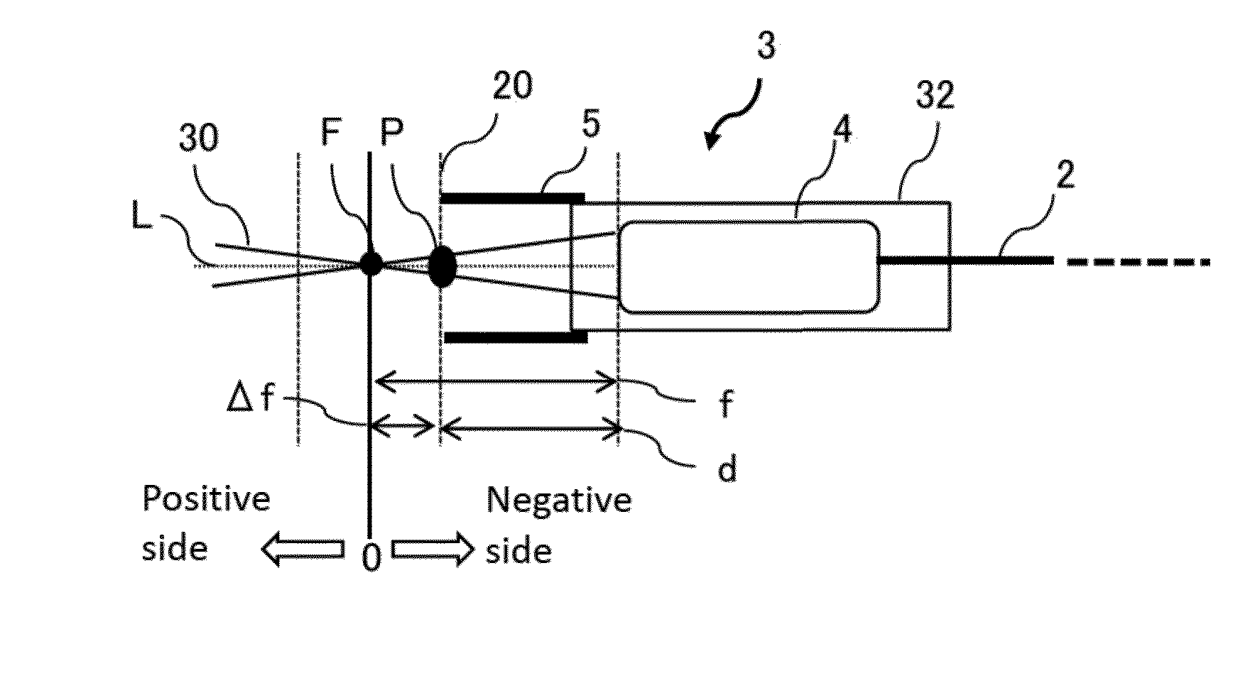
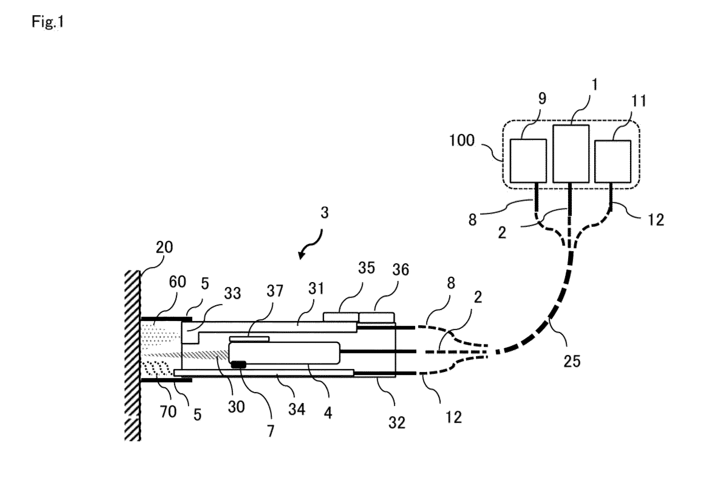
[0070]FIG. 1 is an outline configuration diagram of the laser irradiation apparatus of the first embodiment. This laser irradiation apparatus includes a laser oscillator 1, a fiber 2, a laser head 3, a suction hose 8, and a suction source 9 and may also include a gas supply source 11 and a gas hose 12. The laser head 3 is a small-sized and light-weighted portable one, connected to the laser oscillator 1 via the fiber 2, and can be handled at a work site.

[0071]Moreover, the laser oscillator 1, the suction source 9, and the gas supply source 11 are also apparatuses configured to be transportable and movable and may be mounted on various types of vehicles 100 (a carriage, a vehicle, a barge, a mono-rack (including a monorail and ...

second embodiment

[0104]In the second embodiment, a wedge prism rotatable around an optical axis and a driving means for rotating it are used in the optical system, and the laser beam is irradiated having a conical shape (side surface) flared to the end. A continuous trajectory of the irradiation point of the laser beam on the surface becomes a circle Cl around an intersection between the optical axis and the surface and having a deflection amount of the wedge prism as a radius r1. Hereinafter, the optical system that can scan the irradiation point by a driving mechanism or the like will be also referred to as a scanning optical system.

[0105]Moreover, when the worker holds this laser head for a certain period of time or reciprocally moves it vertically or horizontally as necessary, a coating in a specific range or a wide range can be efficiently removed by laser ablation in a short time.

[0106]FIG. 3 is an outline configuration diagram of the scanning optical system of the laser head of the second emb...

third embodiment

[0128]In the above-described second embodiment, one wedge prism is used for the scanning optical system. On the other hand, in a third embodiment, a wedge prism rotatable around an optical axis and a deflecting means are used for the scanning optical system, and the laser beam is irradiated so as to have a conical shape flared to the end (may be partially hollow). The deflecting means may be a reflective optical element such as a mirror, but a permeable optical element such as a wedge prism is preferably employed. Hereinafter, a case in which the wedge prism is used as the deflecting means will be explained. A continuous trajectory of the irradiation point of the laser beam on the surface has a shape in which a second circle having a deflection amount of a second wedge prism (second wedge prism) as a radius continuously rotates around a moving point on a circumference of a first circle having a deflection amount of a first wedge prism (first wedge prism) as a radius. If the irradiat...


PUM

PropertyMeasurementUnit
Lengthaaaaaaaaaa
Radiusaaaaaaaaaa
Radiusaaaaaaaaaa

Abstract

In order to provide a laser irradiation system, a method for removing a coating, and a laser irradiation apparatus capable of efficiently removing a coating on a surface of a structure and recovering the removed substance using suction, a laser head (3) is configured from an optical system (4) for irradiating laser beam (30), a suctioning means (33) for suctioning removed matter (60) produced at the point where the laser beam (30) is directed, and an attachment (5) configured to be capable of abutting a surface (20) of a structure, the optical system (4) being operated to scan the irradiation point of the laser beam so as to draw a trajectory of a circle having a radius r1 around the optical axis of the laser beam (30) on a surface substantially perpendicular to the optical axis.

Description

TECHNICAL FIELD [0001]The present invention relates to a technology for removing a coating on a surface of a structure by laser irradiation and for suctioning / collecting the removed matter and particularly to a laser irradiation apparatus for removing the coating or the adhering matter by irradiating a laser beam using a portable laser head to a fixed or large structure such as a bridge, a building, a boat, a pipeline and the like as a structure, a laser irradiation system, and a method for removing a coating or adhering matter using such apparatus and system.BACKGROUND ART [0002]In order to use the structures safely for a long time which are difficult to be moved such as a bridge, an express way, an elevated track for a railway, a building, a tank, a machine facility and the like, a coating of painting applied on a surface of a base material (steel material) needs to be periodically peeled off, removed, and re-painted in order to prevent corrosion. As a prior-art method for removi...

Claims


Application Information

Patent Timeline
IPC IPC(8): B23K26/36B23K26/06B23K26/08
CPCB23K26/36B23K26/0639B23K26/0869B23K26/0807B23K26/16B08B7/0035B23K26/0006B23K26/402B23K2103/56Y02E30/30B01J19/12B23K26/00B23K26/04B23K26/06B23K26/08B23K26/14B23K26/064B23K26/082B23K26/037
Inventor TOYOSAWA, HIROYASUTOYOSAWA, KAZUAKIFUJITA, KAZUHISAOKIHARA, SHINICHIRO
Owner TOYOKOH
Learn More