Positive pressure ventilation in enclosed housings

a technology of enclosed housing and positive pressure, which is applied in ventilation systems, lighting and heating apparatus, heating types, etc., can solve the problems of reducing production, odor and moisture buildup in enclosed housings, etc., and achieves the effects of limiting entry of air-borne pathogens, preventing or minimizing entry of contaminated external air, and promoting ventilation

Inactive Publication Date: 2015-03-19
ZIMMERMAN RICHARD
View PDF3 Cites 10 Cited by
  • Summary
  • Abstract
  • Description
  • Claims
  • Application Information

AI Technical Summary

Benefits of technology

[0003]The invention provides a positive pressure ventilation system that utilizes a pressure differential between two chambers within the housing to promote ventilation and limit entry of air-borne pathogens. The invention provides a substantially closed housing having at least two chambers: an overpressure chamber which is maintained at a high positive static pressure, and at least one living chamber which is maintained at a lower positive static pressure relative to the overpressure chamber. The overpressure chamber is in communication with the living chamber through one or more interconnecting air passages that allow for controlled airflow from the overpressure chamber to the living chamber. The pressure differential between the chambers enable unidirection airflow from the overpressure chamber to the living chamber thereby enabling ventilation of the living chamber, and the overall positive static pressure prevents or minimize entry of contaminated external air into the housing. Thus, the invention provides a method for ventilating a substantially closed housing, a ventilation system for a substantially closed housing, as well as a substantially closed housing having positive static pressure and at least one overpressure chamber supplying ventilation air to at least one living chamber through a pressure differential between the chambers.
[0025]In some embodiments, the ventilation system is effective to maintain a pressure differential between the first and second chambers of about 0.05 to about 0.125 inch of water column. In some embodiments, the ventilation system is effective to maintain a pressure differential between the first and second chambers of about 0.1 inch of water column. In some embodiments, the ventilation system is effective to maintain pressure in the first chamber at about 0.2 inch of water column. In some embodiments, the ventilation system is effective to maintain pressure in the second chamber at about 0.1 inch of water column.

Problems solved by technology

Although enclosed housings provide shelter and can be useful as high production facilities for plants and animal husbandry, when poorly ventilated, enclosed housings can be susceptible to odor and moisture buildup, as well as elevated levels of air pollutants such as dust, viruses, bacteria and pollutant gases including ammonia, hydrogen sulfide, carbon monoxide and methane.
This can contribute to the spread of diseases or lead to decreased production.

Method used


Image

  • Positive pressure ventilation in enclosed housings
  • Positive pressure ventilation in enclosed housings
  • Positive pressure ventilation in enclosed housings

Examples


example 1

Positive Pressure Ventilation of an Enclosed Housing

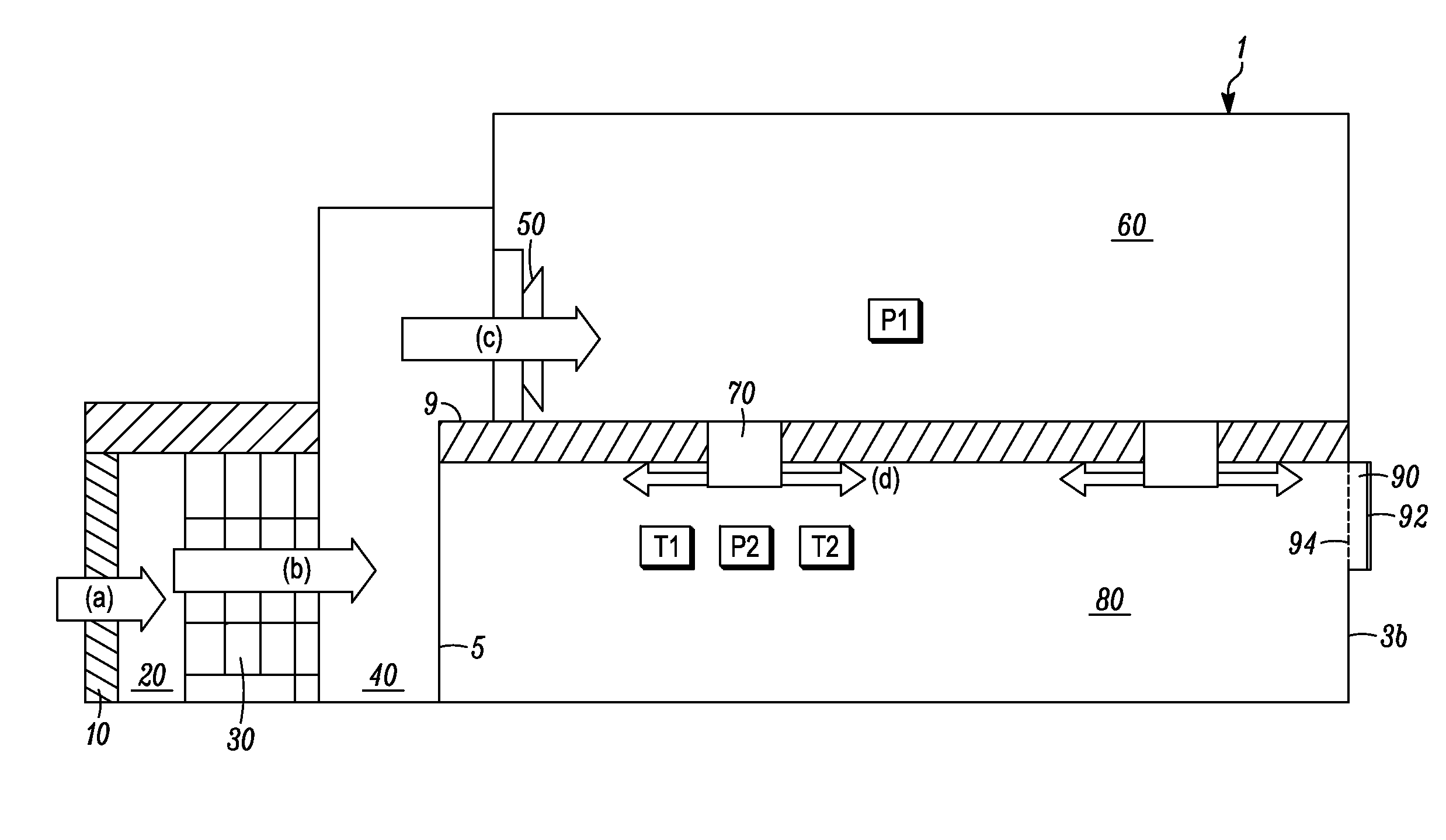
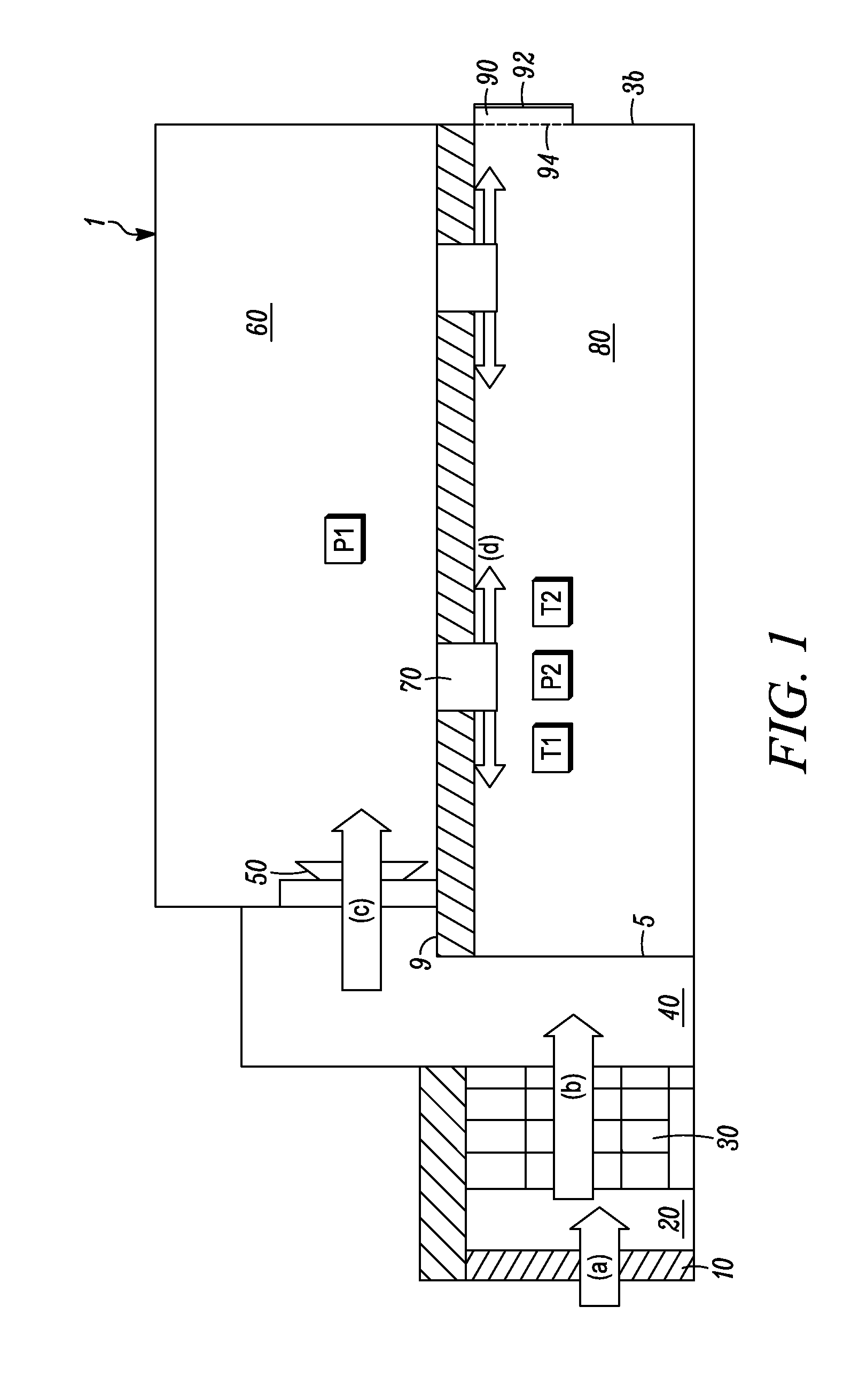
[0070]An embodiment of the invention is shown in FIG. 1, which provides a sectional view of an enclosed housing having a positive pressure ventilation system. In FIG. 1, housing 1 includes living chamber 80 at one level; overpressure chamber 60, a highly pressurized attic space in communication with living chamber 80 through interconnecting air passage 70; air chamber 40, which supplies cooled and filtered air to the one or more of fan 50; and air chamber 20, which contains air that has been cooled by passage through cooling wall 10.

[0071]The direction of airflow through housing 1, represented by the arrows (a), (b), (c), (d) and (e) in FIG. 1, is as follows: (a) external, unfiltered air at ambient temperature is cooled by cooling wall 10 during passage into chamber 20; (b) cooled air in chamber 20 is filtered as it passes through air filter wall 30 into chamber 40; (c) cooled and filtered air in chamber 40 is drawn into overpressu...

example 2

Positive Pressure End Wall Configuration

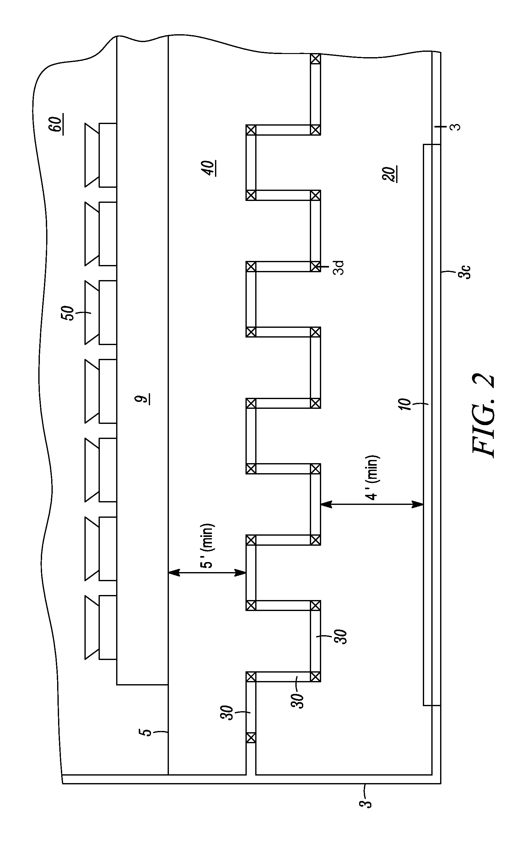
[0076]A diagram representing a partial plan view of an end wall configuration used in an embodiment of the invention is illustrated in FIG. 2. In this embodiment, a plurality of fan 50 for blowing air into overpressure chamber 60 is mounted to building end wall 5 adjacent fan access platform 9. Two air spaces, air space 40 and air space 20, separate the one or more of fan 50 from the exterior of the housing. Air space 40, which occurs between building end wall 5 and filter wall 30, supplies cooled and filtered air to the plurality of fan 50 for ventilation of overpressure chamber 60. Air space 20, which is between filter wall 30 and evaporative cooling wall 10, houses cooled air from the exterior of the housing. Cooling wall 10 separates cooled air in space 20 from the exterior of the housing. Filter wall 30, disposed between building end wall 5 and cooling wall 10, is formed using a plurality of filters arranged at least about five feet from ...

example 3

Exterior Wall Structure of a Living Chamber Outlet in a Positive Pressure Housing

[0078]Living chamber air outlet 90 for the egress of air from living chamber 80 is illustrated in FIG. 3A-3C. Outlet 90 is disposed above housing base wall 3b and includes damper 92 and shutter wall 94. Outlet damper 92 is a 48-inch roll seal or insulated curtain wall outlet damper mounted on the exterior side of the building outlet above base-wall 3. FIG. 3B, which provides a view of outlet 90 from the exterior of the building, shows the insulated curtain / roll seal outlet damper 92 half opened. Shutter wall 94 is a 45-inch ID Z Wall shutter wall located within the opening of outlet 90 above base-wall 3b to provide backdraft protection. FIG. 3C, which provides a view of outlet 90 from the interior of the building, shows that shutter wall 94 is coextensive with the opening of outlet 90, thereby providing an added barrier to infiltration of external air. Base wall 3b is a 48-inch insulated concrete or EPS...


PUM


Abstract

The invention provides a positively pressurized housing ventilated by establishing and / or maintaining a pressure differential between at least two chambers in the housing. The invention also provides a method for ventilating a substantially closed housing that involves establishing and / or maintaining a pressure differential between at least two chambers in the housing.

Description

CROSS-REFERENCE TO RELATED APPLICATIONS[0001]This application claims priority to U.S. provisional application No. 61 / 878,582, filed Sep. 16, 2013, and U.S. provisional application No. 61 / 984,650, filed Apr. 25, 2014, which are incorporated herein by reference in their entirety.BACKGROUND[0002]Enclosed housings provide shelter and a controlled environment through which unfavorable environmental conditions can be mitigated. Enclosed livestock housings, for example, provide animals with shelter from the climate, protection from preditors, as well as airborne pathogens and contaminants. Similarly, enclosed greenhouses can be useful where the growing season is short, light levels are poor, or environmental conditions are marginal for plant growth. Although enclosed housings provide shelter and can be useful as high production facilities for plants and animal husbandry, when poorly ventilated, enclosed housings can be susceptible to odor and moisture buildup, as well as elevated levels of...

Claims


Application Information

Patent Timeline
Patent Type & Authority Applications(United States)
IPC IPC(8): F24F11/02F24F8/10F24F7/003F24F8/96
CPCF24F11/022F24F2011/0004F24F11/0001F24F8/10F24F8/96F24F7/003
Inventor ZIMMERMAN, RICHARD
Owner ZIMMERMAN RICHARD
Why Eureka
Try Eureka