Solar light-heat hybrid power generation system

a hybrid power generation and solar energy technology, applied in the field of solar lightheat hybrid power generation system, can solve the problems of low performance of known thermoelectric transducers, difficult stably providing power, low energy density of solar energy at the surface of the earth, etc., to achieve convenient power generation, improve efficiency, and improve efficiency.

Inactive Publication Date: 2015-03-26
NITTO DENKO CORP
View PDF0 Cites 21 Cited by
  • Summary
  • Abstract
  • Description
  • Claims
  • Application Information

AI Technical Summary

Benefits of technology

[0022]The solar light-heat hybrid power generation system according to the present invention can perform solar heat power generation by rotating the turbine by use of steam generated by the heat of infrared rays which is reflected by the infrared reflective film formed on the surface of the light collecting mirror. In addition, the solar light-heat hybrid power generation system according to the present invention can perform solar light power generation by the solar cell located inside the light collecting mirror by use of light transmitted through the infrared reflective film formed on the surface of the light collecting mirror. Therefore, the solar light-heat hybrid power generation system according to the present invention has an improved efficiency as compared with power generation by use of

Problems solved by technology

However, the solar light power generation systems have problems that the solar energy has a low energy density at a surface of the earth and is easily influenced by the weather conditions, daylight hours or the like.
Namely, there is a problem that it is difficult to stably provide powe

Method used


Image

  • Solar light-heat hybrid power generation system
  • Solar light-heat hybrid power generation system
  • Solar light-heat hybrid power generation system

Examples


modification 1

[0056](Modification 1)

[0057]A solar light-heat hybrid power generation system 100 shown in FIG. 5 is of a Fresnel type. Specifically, the light collecting mirrors 10 in this modification are Fresnel-type mirrors 11. Whereas the surface 10a of each light collecting mirror 10 shown in FIG. 1 is curved, the light collecting mirrors 10 shown in FIG. 5 (Fresnel-type mirrors 11) each have a substantially flat surface 10a. Each Fresnel-type mirror 11 has a groove (not shown) formed therein so that the reflected infrared rays 55 are collected to a heat collecting tube 64 acting as the heat collecting section 60. In this example, the heat collecting tube 64 is plate-shaped.

[0058]In this structural example, the above-described infrared reflective film 20 is formed on the surface 10a of each Fresnel-type mirror 11 having the groove formed therein, so that the infrared rays 55 can be separated from the ultraviolet and visible light 54. Alternatively, the infrared reflective film 20 may have a g...

modification 3

[0063](Modification 3)

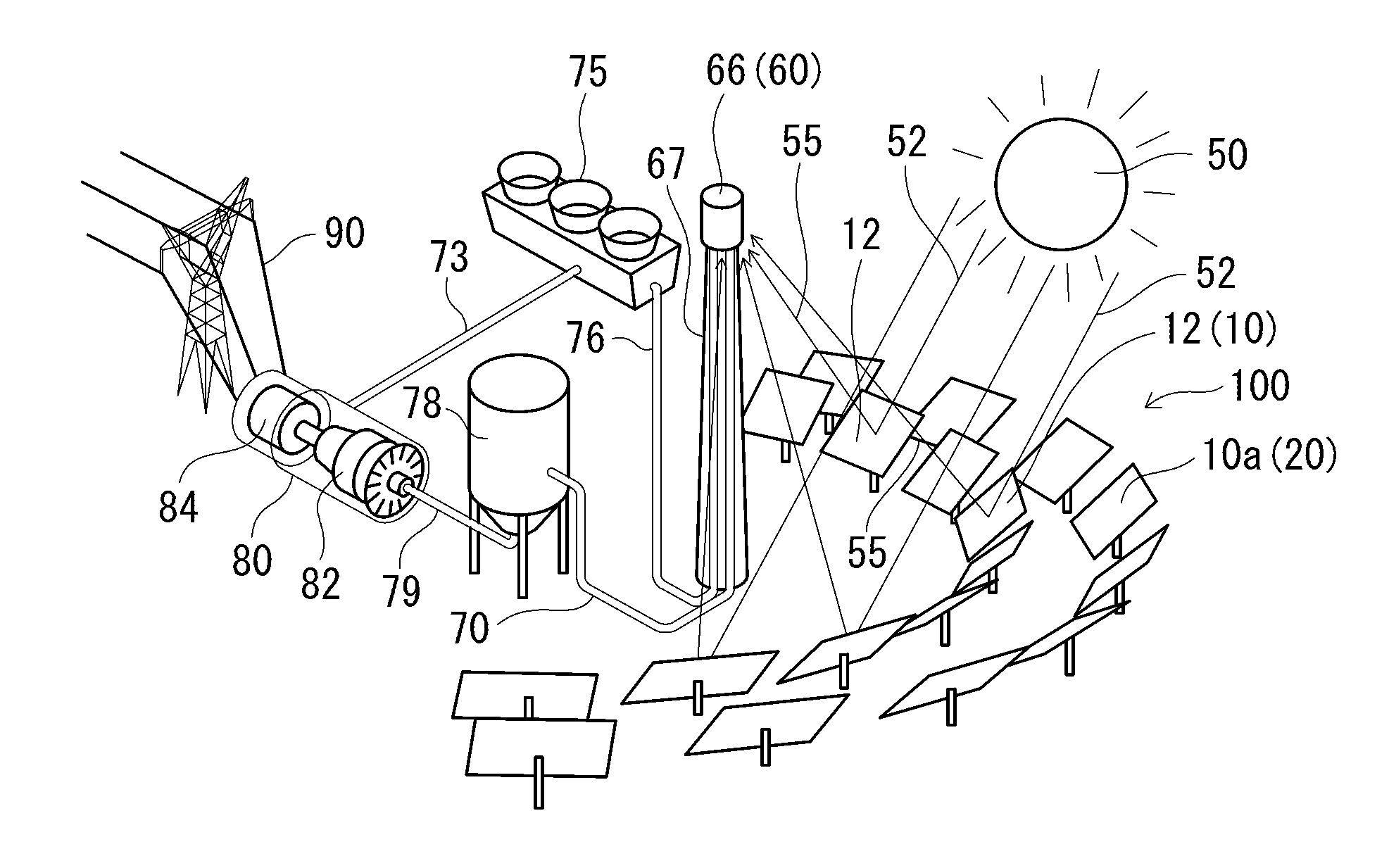
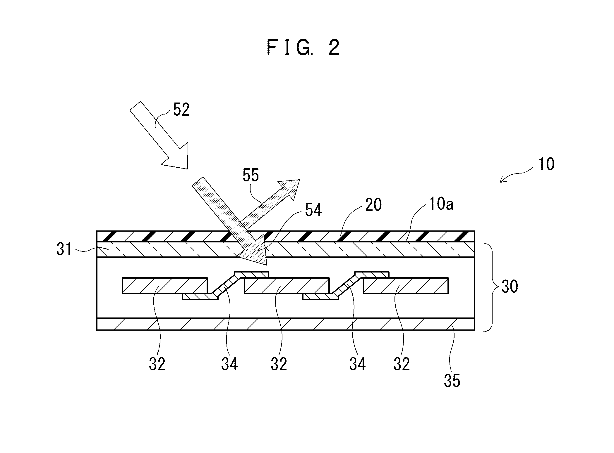
[0064]A solar light-heat hybrid power generation system 100 shown in FIG. 7 is of a dish-type. According to the structure of this modification, the light collecting mirrors 10 are parabola reflective mirrors 14 each having a paraboloidal surface, and the heat collecting sections 60 are heat collecting devices 68 each located at a focal point of the corresponding parabola reflective mirror 14. The heat collecting sections 60 shown in the figure are each secured by support sections (support rods) 69 extending from ends of the corresponding parabola reflective mirror 14. Each parabola reflective mirror 14 has the infrared reflective film 20 formed on a surface 10a thereof As shown in FIG. 2, the solar cell panel 30 including the solar cells 32 is located to the rear of the surface 10a of the parabola reflective mirror 14.

[0065]The power generation system 100 shown in FIG. 7 can generate steam by use of the heat of the heat collecting devices 68. For example, the p...


PUM


Abstract

A solar light-heat hybrid power generation system having an improved efficiency is provided. A solar light-heat hybrid power generation system (100) that performs power generation by use of sunlight (52) and solar heat (52) includes a light collecting mirror (10) having an infrared reflective film (20) formed on a surface (10a) thereof; a heat collecting section (60) that collects infrared rays (55) reflected by the infrared reflective film (20) on the surface (10a) of the light collecting mirror (10); a power generator (84) including a turbine (82) rotatable by steam generated by heat collected to the heat collecting section (60); and a solar cell panel (30) including a solar cell (32) located inside the light collecting mirror (10).

Description

TECHNICAL FIELD[0001]The present invention relates to a solar light-heat hybrid power generation system, and specifically to a power generation system utilizing optical energy and thermal energy from sunlight.[0002]The present application claims the benefit of priority based upon Japanese Patent Application No. 2011-289109 filed on Dec. 28, 2011, the entirety of which is incorporated herein by reference.BACKGROUND ART[0003]Recently, as the global environmental problem and the problem of energy exhaustion caused by increase in fossil fuel consumption or the like have become increasingly serious, clean energy which does not accompany much fossil fuel consumption has been desired. In addition, there is an increasing tendency of avoiding dependence on nuclear power generation in consideration of the influence of the Great East Japan Earthquake. In such a situation, power generation utilizing solar energy has been spread and is attracting more and more attention.[0004]Power generation sy...

Claims


Application Information

Patent Timeline
IPC IPC(8): H01L31/052H01L31/054G02B5/28H01L31/0216F24S23/70
CPCH01L31/0525G02B5/282H01L31/0547H01L31/02167Y02E10/46F03G6/001F03G6/065Y02E10/52Y02E10/60H02S40/44F24S23/71F24S23/74F24S2023/86F24S23/82F24S23/77Y02E10/40
Inventor MATSUSHIMA, RYOICHI
Owner NITTO DENKO CORP
Why Eureka
Try Eureka