Method for manufacturing a tube sheet and heat exchanger assembly for a pool reactor or pool condenser; corresponding tube sheet and heat exchanger assembly

a technology of pool reactor and heat exchanger, which is applied in the direction of indirect heat exchanger, manufacturing tools, lighting and heating apparatus, etc., can solve the problems of inability to manufacture tube sheets of only austenitic-ferritic duplex stainless steel to have the proper and the inability to forged tubes. to achieve the effect of corrosion resistance over the entire thickness and high cos

Active Publication Date: 2015-03-26
STAMICARBON BV
View PDF3 Cites 27 Cited by
  • Summary
  • Abstract
  • Description
  • Claims
  • Application Information

AI Technical Summary

Benefits of technology

[0004]According to one aspect of the invention a method for manufacturing a tube sheet and heat exchanger assembly for a shell and tube type heat exchanger such as a pool reactor or pool condenser for use in an apparatus for the production of urea from ammonia and carbon dioxide is provided. The method comprises manufacturing of the tube sheet from a carbon steel material grade and providing said tube sheet, on a shell side and a tube side thereof, with a corrosion protective layer of an austenitic-ferritic duplex stainless steel grade. The heat exchanger comprises at least one U-shaped tube of an austenitic-ferritic duplex stainless steel grade. The method further comprises inserting at least two sleeves of an austenitic-ferritic duplex stainless steel grade through the tube sheet such that both ends of the sleeve extend in a direction away from the tube sheet. The method comprises connecting the sleeves, at least the opposing ends thereof, to at least the protective layers of the tube sheet and then connecting both ends of the at least one U-shaped tube to the respective ends of the sleeves. With such a method according to the invention, connecting of the U-shaped tubes of the bundle comprises two steps. By first inserting sleeves into the tube sheet, connecting of the sleeves at both ends thereof to the protective layers provided on both surfaces of the tube sheet, is relatively simple. After all, both ends of the sleeves can be reached easily, in contrary to when the U-shaped tubes need to be connected to the tube sheet directly. Connecting of the ends of the U-shaped tubes to the ends of the sleeves can be obtained relatively simple as well. To connect the ends of a U-shaped tube to the ends of the sleeves, the ends of the U-shaped tube are positioned against the respective ends of the sleeves such that both tubes of the U-shaped tube are in line with the respective sleeves. Subsequently, the respective ends of the sleeves and ends of the tubes are interconnected, for instance by means of internal bore welding.

Problems solved by technology

This would however not be possible in case the entire tube sheet would be manufactured from the austenitic-ferritic duplex stainless steel grade.
Besides, with a thickness of more than 300 mm, a tube sheet of solely austenitic-ferritic duplex stainless steel can not be forged to have the proper corrosion resistance over the entire thickness, thus also inside the hole extending though the entire tube sheet.
Furthermore, this would be an expensive alternative.
Even materials with an extremely high corrosion resistance will be susceptible to crevice corrosion in case of stagnant corrosive fluid in any crevice between the tube and the tube sheet.

Method used


Image

  • Method for manufacturing a tube sheet and heat exchanger assembly for a pool reactor or pool condenser; corresponding tube sheet and heat exchanger assembly
  • Method for manufacturing a tube sheet and heat exchanger assembly for a pool reactor or pool condenser; corresponding tube sheet and heat exchanger assembly
  • Method for manufacturing a tube sheet and heat exchanger assembly for a pool reactor or pool condenser; corresponding tube sheet and heat exchanger assembly

Examples


Embodiment Construction

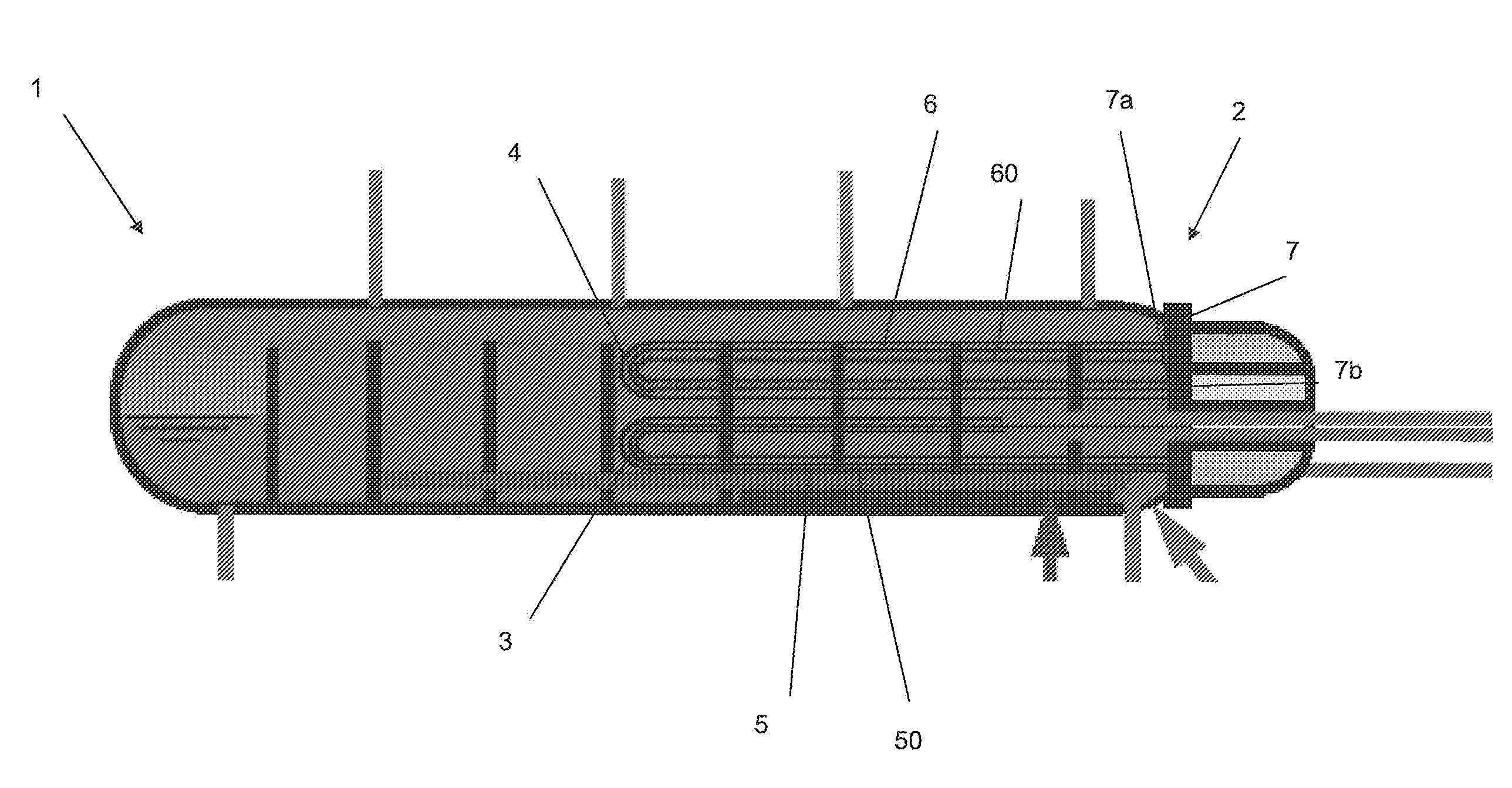
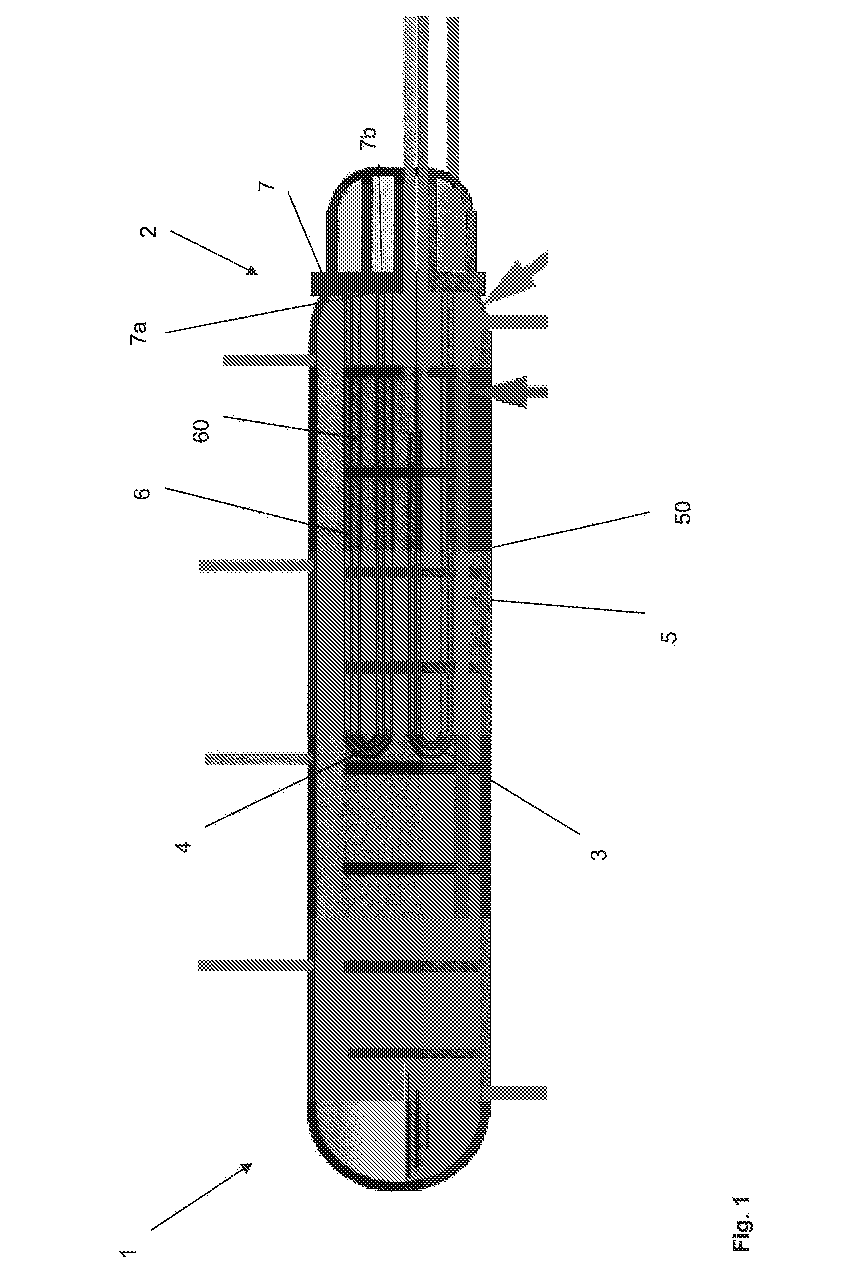
[0021]In FIG. 1, an example of a pool reactor 1 according to an embodiment of the invention is shown. Such a pool reactor may be used in a urea plant for the production of urea from ammonia and carbon dioxide in a urea plant. The pool reactor 1 may be a shell and tube heat exchanger. Such a heat exchanger may be used as a pool reactor or a pool condenser, for instance as a horizontal submerged reactor or condenser. The pool reactor 1 comprises a vessel, which in use, is placed substantially horizontally, with a first heat exchanging section 3 and a second heat exchanging section 4. In the shown embodiment, both heat exchanging sections 3, 4 comprise a substantially U-shaped tube bundle 5, 6. The first U-shaped tube bundle 5 is configured for condensation of carbamate and for subsequently decomposing of ammonium carbamate into NH3 and CO2 by means of the heat that is released during said condensation.

[0022]The second U-shaped tube bundle 6 is configured to produce low pressure steam....


PUM

PropertyMeasurementUnit
thicknessaaaaaaaaaa
thicknessaaaaaaaaaa
thicknessaaaaaaaaaa

Abstract

The present application relates to a method of manufacturing a tube sheet (7) and heat exchanger assembly for a pool reactor or pool condenser for use in the production of urea from ammonia and carbon dioxide, wherein the method comprises manufacturing of the tube sheet (7) from a carbon steel material grade and providing said tube sheet (7) with corrosion protective layers (8, 9) of an austenitic- ferritic duplex stainless steel grade, wherein the heat exchanger comprises at least one U-shaped tube (13) of an austenitic-ferritic duplex stainless steel grade, the method further comprises inserting at least two sleeves (11) of an austenitic-ferritic duplex stainless steel grade through the tube sheet (7) such that both ends of the sleeve (11) extend in a direction away from the tube sheet (7), the method further comprises connecting the sleeves (11), at least the opposing ends thereof, to at least the protective layers (8,9) of the tube sheet (7) and finally, connecting both ends of the at least one U-shaped tube (13) to the respective sleeves (11).

Description

FIELD OF THE INVENTION[0001]The present invention relates to the field of the production of urea from ammonia and carbon dioxide in a urea plant containing a high-pressure synthesis section. In particular the invention relates to the field of manufacturing a tube sheet and heat exchanger assembly for a pool reactor or pool condenser for the production of urea from ammonia and carbon dioxide in a urea plant.BACKGROUND[0002]For the production of urea and carbon dioxide in a urea plant, such a plant may comprise a high pressure stripper, a high pressure carbamate condenser, pool condenser or pool reactor. Such a pool condenser or pool reactor may be of the shell and tube type comprising substantially u-shaped tube bundles extending through a tube sheet. Such a urea plant is for instance described in WO 2009 / 141346. The shell side of the known pool reactor or pool condenser is filled with high pressure process medium. The U-shaped tube bundle provided in the reactor or condenser is fill...

Claims


Application Information

Patent Timeline
Patent Type & Authority Applications(United States)
IPC IPC(8): F28F9/18F28F19/06B21D53/08
CPCF28F9/18F28F19/06B21D53/08B01J3/04B01J19/0013B01J19/006B01J19/02B01J19/24B23K31/027F28D7/06F28F9/185F28F21/083B01J2219/024B01J2219/0286B01J2219/182F28D2021/0022B23K2103/04B23K2101/14B23K2103/18B01J2219/00768B01J2219/00081B01J2219/00256B23K2103/05Y10T29/49373Y10T29/49968Y02P20/141B01J2219/192
Inventor SCHEERDER, ALEXANDER ALEIDA ANTONIUS
Owner STAMICARBON BV
Why Eureka
Try Eureka