Current mode class ab low-noise amplifier and method of active cable termination

a low-noise amplifier and active cable technology, applied in the field of medical ultrasonic imaging systems, can solve the problems of limiting the dynamic range of an lna, noise and distortion, and the power dissipation of a single common-gate ultrasound lna is quite substantial, and achieves the effect of minimizing the influence of technological variations on the performance of class ab transconductor

Inactive Publication Date: 2015-04-02
MICROCHIP TECH INC
View PDF0 Cites 19 Cited by
  • Summary
  • Abstract
  • Description
  • Claims
  • Application Information

AI Technical Summary

Benefits of technology

[0032]A further aspect of the present invention is to propose method and means for minimizing the influence of the technological variations on the class AB transconductor performance. To achi

Problems solved by technology

There are two factors limiting dynamic range of an LNA: noise and distortions.
However, operating in a class A voltage mode, power dissipation of a single common-gate ultrasound LNA is quite substantial.
Removal of a physical te

Method used


Image

  • Current mode class ab low-noise amplifier and method of active cable termination
  • Current mode class ab low-noise amplifier and method of active cable termination
  • Current mode class ab low-noise amplifier and method of active cable termination

Examples


Embodiment Construction

[0045]A description of the present invention is given with reference to FIGS. 7-11 wherein like parts are designated with like numerals throughout.

[0046]FIG. 7 depicts a unipolar Voltage-to-Current (V / I) conversion circuit 700. The circuit 700 is primarily responsive for converting the negative portion of AC voltage signals into current ones and comprises a folded cascode amplifier formed of a common-gate (CG) stage followed by another CG stage complementary to the preceding. Said conversion circuit encompasses:[0047]voltage input node labeled VIN,[0048]N-channel common-gate stage 701,[0049]first bias current source labeled IBIAS1,[0050]decoupling capacitor 703,[0051]second bias current source labeled IBIAS2,[0052]P-channel common-gate stage 705,[0053]voltage bias source labeled VBIAS, and[0054]output current node labeled IOUTP.

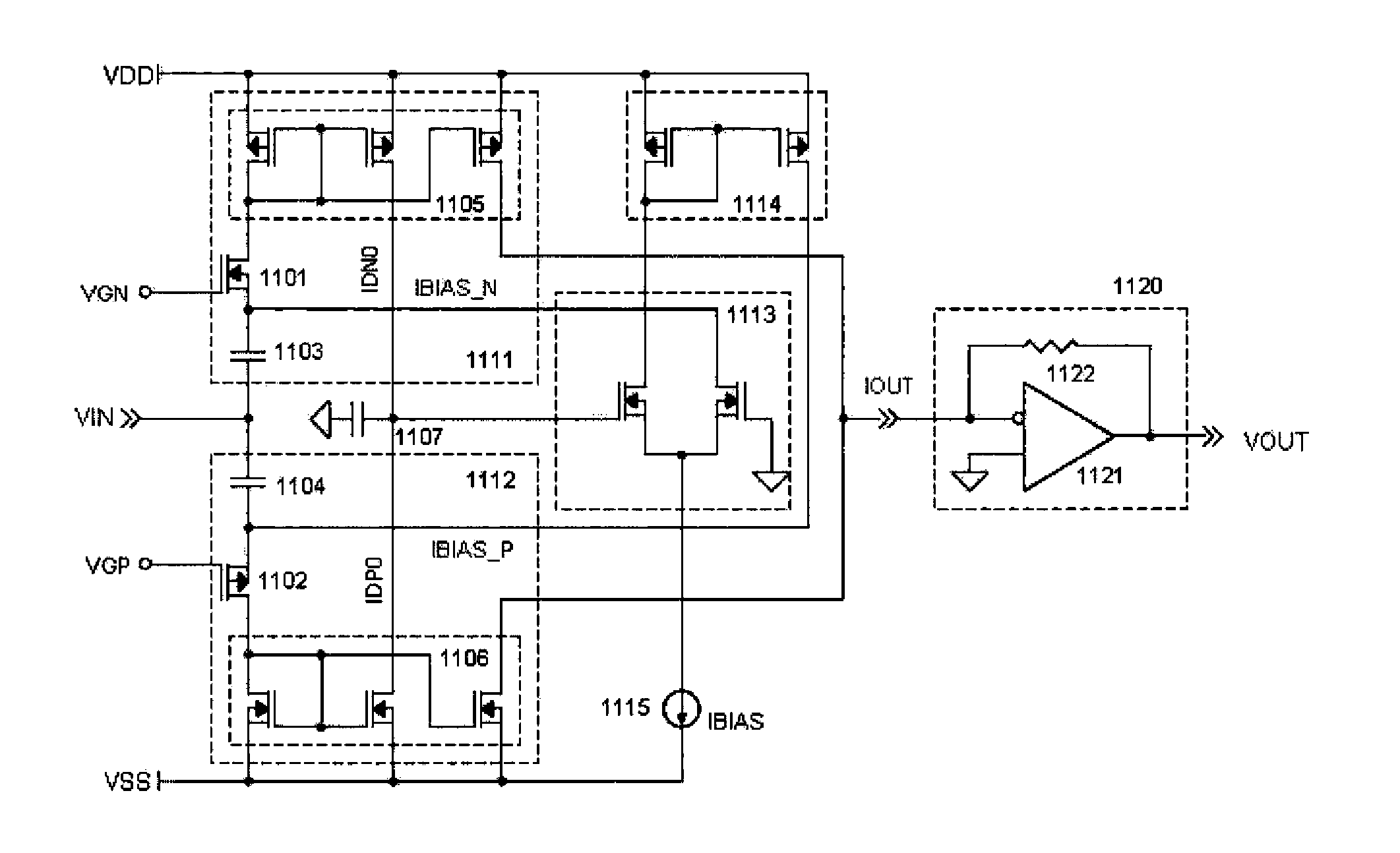
[0055]The first embodiment of a Class AB ultrasound LNA is shown in FIG. 8. This LNA consists of a transconductor operating in Class AB followed by a current...


PUM


Abstract

This invention relates to medical ultrasonic imaging systems and, in particular, phased array imaging systems operating in different scan formats and imaging modalities. More specifically, the invention relates to the front-end processing of ultrasonic echoes.

Description

TECHNICAL FIELD[0001]This invention relates to medical ultrasonic imaging systems and, in particular, phased array imaging systems operating in different scan formats and imaging modalities. More specifically, the invention relates to the front-end processing of ultrasonic echoes.BACKGROUND OF THE INVENTION[0002]With the exception of CW Doppler, ultrasonic imaging systems use a pulse-echo method alternately functioning in two basic modes: transmit and receive. In the transmit mode, one or more transducer elements are excited by electrical pulses emitted by a transmitter, TX. During propagation within the tissue, acoustic waves are echoed back towards the transducer. Then, in the receive mode, ultrasound echoes are converted by the same transducer element into electrical signals. These analog signals are directed to a front-end, which typically comprises a low-noise amplifier (LNA) and time-gain compensation (TGC) circuitry followed by an anti-aliasing filter (AAF) and an analog-to-d...

Claims


Application Information

Patent Timeline
IPC IPC(8): H03F3/21H03F3/26H03F3/45H03F3/193
CPCH03F3/21H03F3/193H03F2203/45262H03F3/45071H03F2203/45112H03F3/265H03F3/3028H03F3/45183H03F2203/30105H03F2203/30138
Inventor SHIFRIN, LAZAR
Owner MICROCHIP TECH INC
Why Eureka
Try Eureka