Substrate processing apparatus and substrate processing method

a processing apparatus and substrate technology, applied in the field of semiconductor technology, can solve the problems of many problems in the processing of substrates with liquids, and achieve the effects of suppressing the reduction of throughput, and stably controlling the amoun

Active Publication Date: 2015-04-02
DAINIPPON SCREEN MTG CO LTD
View PDF8 Cites 17 Cited by
  • Summary
  • Abstract
  • Description
  • Claims
  • Application Information

AI Technical Summary

Benefits of technology

[0026]While the substrate continues to be held by the substrate holder, the front surface peripheral area of this substrate and the back surface of this substrate are processed continuously. This can process both the front surface peripheral area and the back surface of the substrate while suppressing reduction of a throughput. Meanwhile, a processing liquid is discharged toward each of the front surface peripheral area and the back surface of the substrate. This can stably control the amount of a processing liquid held on each of the front surface peripheral area and the back surface. Additionally, a processing liquid is supplied to the back surface after a processing liquid is supplied to the front surface peripheral area. Thus, if the processing liquid supplied to the front surface peripheral area is splashed from the substrate and then adheres to the back surface, the processing liquid adhering to the back surface can be washed away with the processing liquid supplied to the back surface of the substrate thereafter. In this way, both the front surface peripheral area and the back surface can be processed properly. As a result, the front surface peripheral area and the back surface can be processed properly while reduction of a throughput is suppressed.
[0027]In the substrate processing apparatus according to a different aspect of this invention, the controller makes the substrate holder reduce a rotation speed of the substrate after stopping discharge of the processing liquid from the discharge head for peripheral area and before starting discharge of the processing liquid from the back surface processing unit.
[0028]The rotation speed of the substrate is reduced before the processing liquid is discharged toward the back surface. Specifically, the substrate is rotated at a relatively high speed while the processing liquid is supplied to the front surface peripheral area and is rotated at a relatively low speed while the processing liquid is supplied to the back surface. This structure can suppress entry of the processing liquid supplied to the front surface peripheral area into a device region. This structure can also suppress entry of the processing liquid supplied to the back surface into the device region to be caused if this processing liquid goes into the front surface of the substrate.

Problems solved by technology

Processing a substrate with liquid has encountered many problems.
Such adhesion of the processing liquid may become a cause for some problem.

Method used


Image

  • Substrate processing apparatus and substrate processing method
  • Substrate processing apparatus and substrate processing method
  • Substrate processing apparatus and substrate processing method

Examples


first preferred embodiment

1. Substrate Processing System 100

[0081]

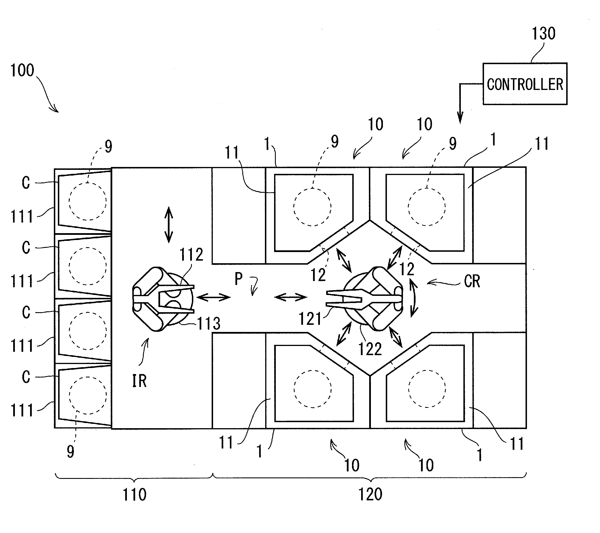
[0082]The structure of a substrate processing system 100 is described below by referring to FIG. 1. FIG. 1 is a diagrammatic plan view schematically showing the substrate processing system 100.

[0083]The substrate processing system 100 is a system to successively process multiple substrates 9 one by one. In the below, a substrate 9 to be processed in the substrate processing system 100 is a circular semiconductor wafer, for example.

[0084]The substrate processing system 100 includes multiple cells (processing blocks) (more specifically, indexer cell 110 and processing cell 120) arranged in juxtaposition, and a controller 130 to control each operating mechanism and the like of the cells 110 and 120.

[0085]110>

[0086]The indexer cell 110 is a cell to transfer an unprocessed substrate 9 received from outside the system to the processing cell 120 and to transport a processed substrate 9 received from the processing cell 120 to the outside of the syste...

second preferred embodiment

1. Structure of Substrate Processing Apparatus 1

[0315]The following describes the structure of a substrate processing apparatus 1 of a second preferred embodiment by referring to FIGS. 26 to 28. FIG. 26 is a diagrammatic perspective view of the substrate processing apparatus 1 showing a condition where semicircular members 61 and 62 forming a guard member 60, a cup 31, and a discharge head 51 for peripheral area are placed in their respective retreat positions. FIG. 27 is also a diagrammatic perspective view of the substrate processing apparatus 1 showing a condition where the guard member 60, the cup 31, and the discharge head 51 are placed in their respective processing positions. FIG. 28 is a schematic view describing the structure of the substrate processing apparatus 1. The substrate processing apparatus 1 is installed for example on the aforementioned substrate processing system 100. The substrate processing apparatus 1 is to process the aforementioned substrate 9, for example...

third preferred embodiment

1. Structure of Substrate Processing Apparatus 1

[0416]The following describes the structure of a substrate processing apparatus 1 of a third preferred embodiment by referring to FIGS. 3, 4 and 38. FIG. 3 is a diagrammatic perspective view of the substrate processing apparatus 1 showing a condition where semicircular members 61 and 62 forming a guard member 60, a cup 31, and a processing head 51 for peripheral area are placed in their respective retreat positions. FIG. 4 is also a diagrammatic perspective view of the substrate processing apparatus 1 showing a condition where the guard member 60, the cup 31, and the processing head 51 are placed in their respective processing positions. FIG. 38 is a schematic view describing the structure of the substrate processing apparatus 1. The substrate processing apparatus 1 is installed for example on the aforementioned substrate processing system 100. The substrate processing apparatus 1 is to process the aforementioned substrate 9, for examp...


PUM

PropertyMeasurementUnit
widthaaaaaaaaaa
temperatureaaaaaaaaaa
distanceaaaaaaaaaa

Abstract

A substrate processing apparatus includes: a substrate holder to hold a substrate in a horizontal posture while rotating the substrate about a vertical rotary axis passing through the center of a plane of the substrate; a guard member having a shape extending along at least part of a surface peripheral area of the substrate, the guard member being placed in a position close to the surface peripheral area of the substrate held by the substrate holder in a noncontact manner; a cup being a tubular member with an open top end, the cup being provided so as to surround the substrate held by the substrate holder and the guard member together; and a nozzle from which a processing liquid is discharged to the surface peripheral area of the substrate held by the substrate holder. The nozzle is placed on a side opposite the cup with respect to at least part of the guard member.

Description

BACKGROUND OF THE INVENTION[0001]1. Field of the Invention[0002]The present invention relates to a technique of processing a semiconductor wafer, a glass substrate for a liquid crystal display, a glass substrate for a plasma display, a substrate for an optical disk, a substrate for a magnetic disk, a substrate for a magnetooptical disk, a glass substrate for a photomask, and a substrate for a solar cell (these substrates are hereinafter simply called “substrates”), for example.[0003]2. Description of the Background Art[0004]There has conventionally been a substrate processing apparatus that supplies a processing liquid to a rotated substrate to process the substrate with the liquid (see Japanese Patent Application Laid-Open Nos. 7-115081 (1995), 2000-235948 and 2002-359220).[0005]Processing a substrate with liquid has encountered many problems. As an example, while a processing liquid is supplied to part of the substrate such as an area (surface peripheral area) in a surface of the ...

Claims


Application Information

Patent Timeline
Patent Type & Authority Applications(United States)
IPC IPC(8): H01L21/306H01L21/67
CPCH01L21/67075H01L21/30604H01L21/67028H01L21/67051H01L21/68728H01L21/02087H01L21/0209B08B3/02H01L21/68764
Inventor FUJIWARA, TOMONORISHIBAYAMA, NOBUYUKIYOSHIDA, YUKIFUMISHIBATA, TETSUYANAKANO, AKIYOSHI
Owner DAINIPPON SCREEN MTG CO LTD
Why Eureka
Try Eureka