
Microneedle and microneedle array

a microneedle and array technology, applied in the field of microneedle and microneedle array, can solve the problems of inability to effectively administer a suitable amount of drugs, inconvenient thermoplastic resin application, poor puncture properties of the microneedle and the microneedle array, etc., to achieve excellent puncture properties, improve the puncture effect, and facilitate the penetration of the epidermal layer of the patien

Active Publication Date: 2015-04-02
MEDRX CO LTD
View PDF0 Cites 10 Cited by
  • Summary
  • Abstract
  • Description
  • Claims
  • Application Information

AI Technical Summary

Benefits of technology

This patent describes a new type of needle that can be poked into the skin without causing pain. These needles can be used to deliver medicine through the skin without needing a injection. The needles are easy to use and can carry large amounts of medicine with them. This invention also includes a device made up of these needles. This technology may make it easier to treat skin conditions without causing any additional pain or discomfort to the patient.

Problems solved by technology

However, since the area to which a drug can be applied is limited to the surface of the skin, a patient experiences a daily basis the fall-off of the applied drug by perspiration or contact with foreign matter, thereby making it difficult to administer a suitable amount of a drug effectively.
However, the Puncture properties of the microneedle and the microneedle array are not satisfactory.
However, since the method disclosed by Patent Document 3 makes use of volume shrinkage when a polymer solution is applied to a stamper to be gelled and dried, it is not suitable for a thermoplastic resin.

Method used


Image

  • Microneedle and microneedle array
  • Microneedle and microneedle array
  • Microneedle and microneedle array

Examples


example 1

Two-Stage Needle: PGA, Normal Fixation

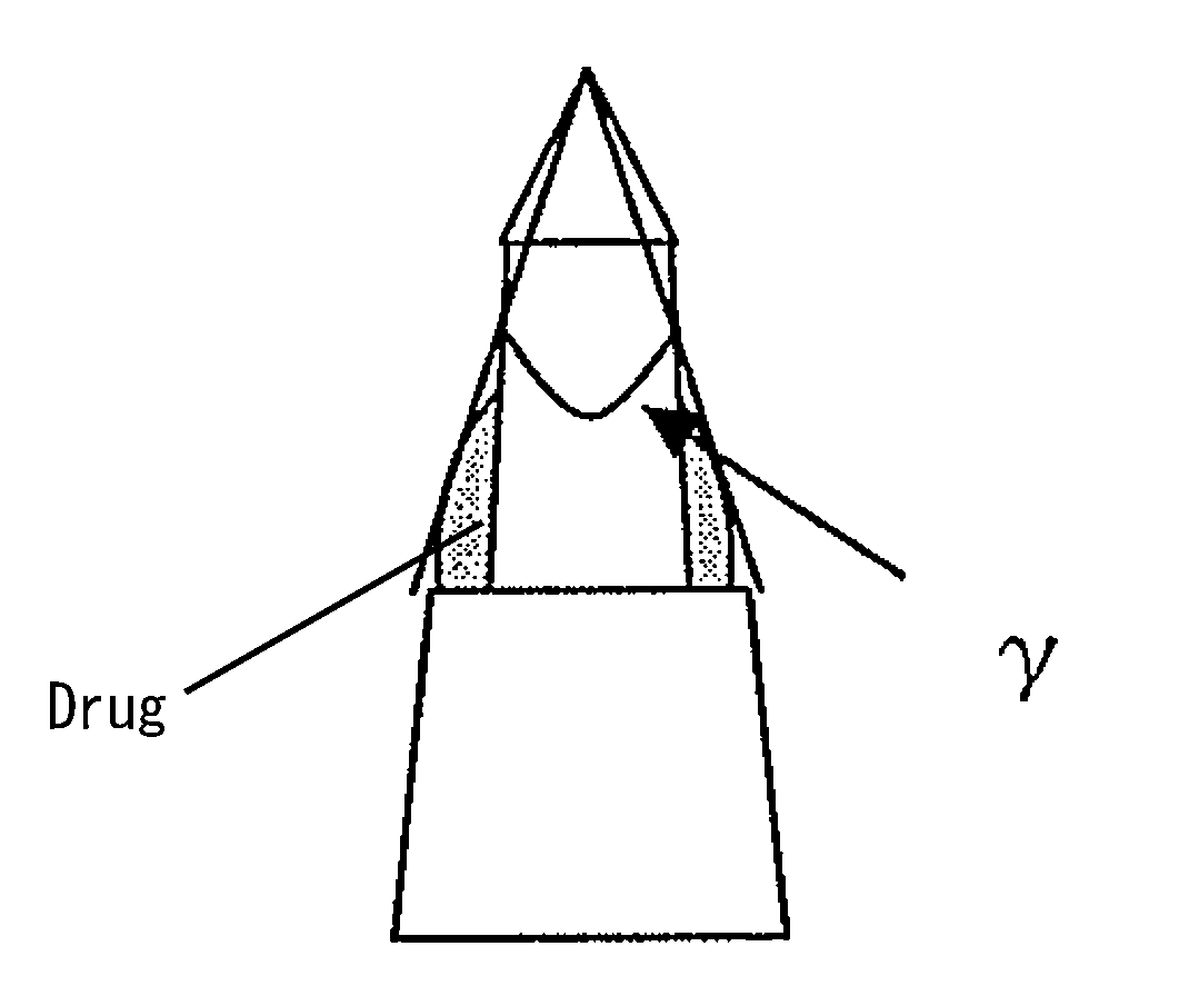
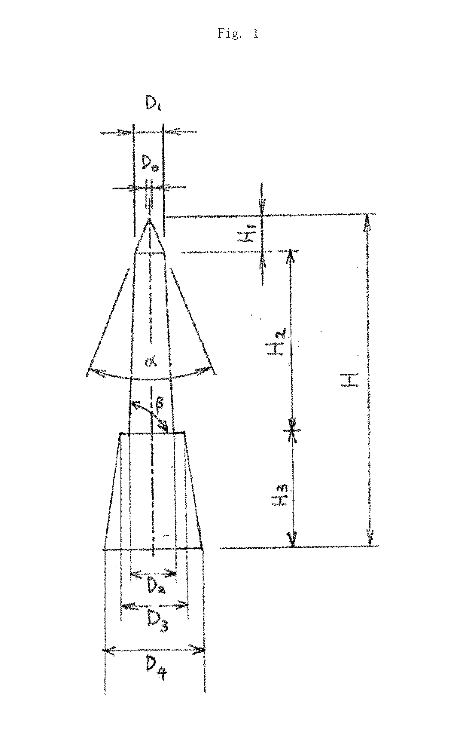
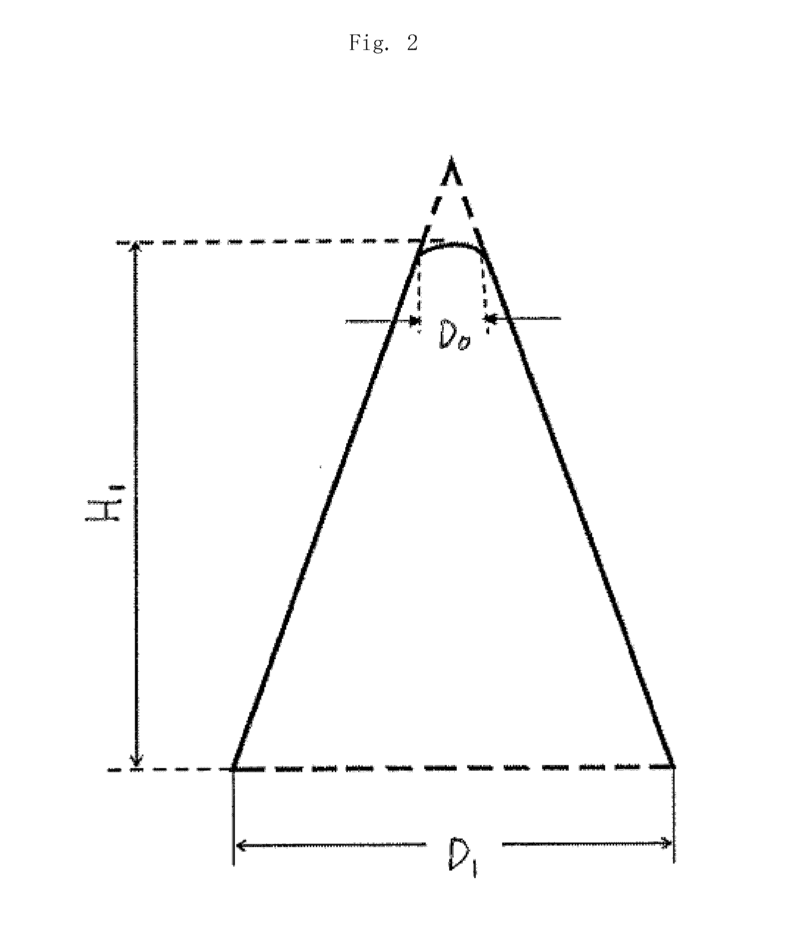
[0096]The microneedle was manufactured as follows. A mold was manufactured by cutting a metal to produce a master which is the basis of the mold and inverting the master by nickel electrocasting. As for the shape of the microneedle, the tip diameter (D0) was 7 μm, the diameter (D1) of the bottom surface of the top section was 60 μm, the diameter (D2) of the bottom surface of the shaft section was 100 μm, the diameter (D4) of the bottom surface of the base section was 150 μm, the overall height (H) was 600 μm, the height (H1) of the top section was 65 μm, the height (H2) of the shaft section was 240 μm, the tip apex angle (α) was 45°, and 120 needles were used.

[0097]For the molding of the microneedle, Micro-Nano Melt Transcription Molding Machine (registered trademark) of The Japan Steel Works, Ltd. was used. Polyglycolic acid (PGA) was used as the resin, molten at 260° C. and applied to a 200° C. mold. Then, the resin was pressed at a pressure o...

example 2

Two-Stage Needle: SUS, Normal Fixation

[0101]A microneedle having the same shape as that of Example 1 was manufactured by cutting stainless steel, and a drug was fixed to the microneedle by the same method as in Example 1 to make the above evaluations in the same manner as in Example 1.

example 3

Two-Stage Needle: PGA, Fixation of a Small Amount

[0102]The microneedle manufactured in Example 1 was used to fix a drug by the same method as in Example 1 but the number of times of immersion was 3. The above evaluations were made

[0103]The results are shown in Table 1. In Table 1, a describing method for specifying the shape of the two-stage needle of the present invention is employed and does not match a method for a one-stage needle. For example, when the one-stage needle is described by the method for the two-stage needle, D2=D3. In the case of the two-stage needle, D23.


PUM


Abstract

The present invention relates to a microneedle and a microneedle array. More specifically, it relates to a microneedle and a microneedle array capable of injecting a drug into the surface layer or horny layer of the skin easily, safely and efficiently.

Description

TECHNICAL FIELD[0001]The present invention relates to a microneedle and a microneedle array. More specifically, it relates to a microneedle and a microneedle array capable of injecting a drug into the surface layer or horny layer of the skin easily, safely and efficiently.BACKGROUND ART[0002]Heretofore, to administer a drug or the like to the biological surface of a patient, that is, the surface of the skin or mucous membrane, a method of applying a liquid substance or a powdery substance has been employed in most cases. However, since the area to which a drug can be applied is limited to the surface of the skin, a patient experiences a daily basis the fall-off of the applied drug by perspiration or contact with foreign matter, thereby making it difficult to administer a suitable amount of a drug effectively.[0003]As an alternative to the application of a drug to the biological surface, there is proposed the administration of a drug into a living body by means of a microneedle. Also...

Claims


Application Information

Patent Timeline
IPC IPC(8): A61M37/00
CPCA61M37/0015A61M2037/0061A61M2037/0046A61K9/0021A61M2037/0053
Inventor TOYOHARA, KIYOTSUNATANAKA, TAISHIKOHNO, KAZUKIODA, TAKASHIMASAOKA, KOICHIKOBAYASHI, KATSUNORIISHIBASHI, MASAKIHAMAMOTO, HIDETOSHI
Owner MEDRX CO LTD
Learn More