
Methods and apparatus for reducing scan time of phase contrast MRI

Active Publication Date: 2015-04-09
BETH ISRAEL DEACONESS MEDICAL CENT INC
View PDF4 Cites 22 Cited by
  • Summary
  • Abstract
  • Description
  • Claims
  • Application Information

AI Technical Summary

Benefits of technology

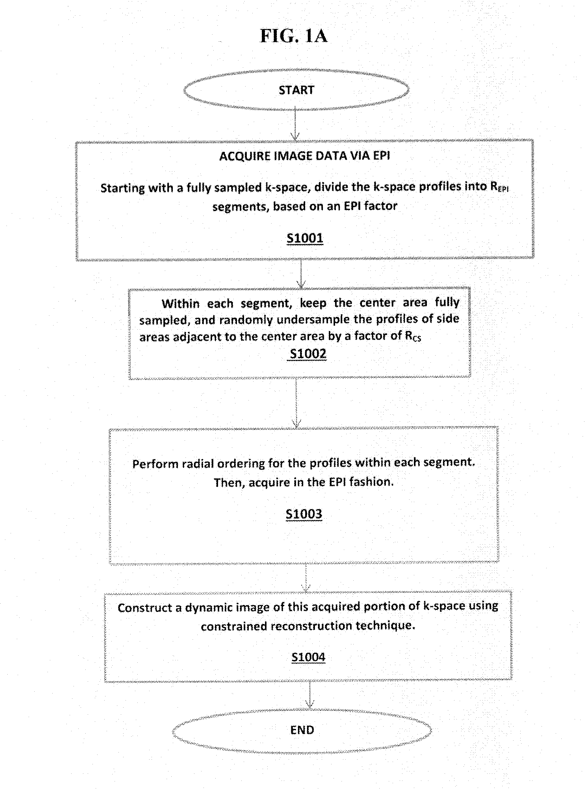
The present invention provides a method and apparatus for reducing scan time in dynamic magnetic resonance imaging (MRI) associated with obtaining and processing k-space. This is achieved by combining a data sampling strategy called EPI with the use of a randomly undersampled reconstruction to reduce eddy currents. The invention can be applied to any type of reconstruction, including y-z patterns or 3D k-space sampling patterns. The use of EPI allows for an increase in sparsity, which can be easily sparsified using a transform domain. The method can also remove residual artifacts from flow images and save time by reducing the application of long flow encoding gradients. The overall objective of the invention is to provide a faster and more efficient way to obtain high-quality dynamic MRI images.

Problems solved by technology

However, conventionally, there have been some issues with EPI.
While the acquisition time per slice with EPI can be on order of 100 ms / slice, there is a rather limited spatial resolution.
Not only does this extended time increase costs of operation, but also discourages the use of such scanning as the accuracy and validity of such resulting data.
However, conventionally, there have been some issues with EPI.
While the acquisition time per slice with EPI can be on order of 100 ms / slice, there is a rather limited spatial resolution.
There is difficulty in providing high-resolution MRI of an object when there is motion is involved, for example, an MRI of organs such as the coronary arteries, lungs, etc. associated with both cardiac and respiratory motion.
While there can be temporal triggering as the motion tends to be generally repetitive motion, the amount of scan time that can be needed to obtain an acceptable image can be excessive.
Moreover, heretofore it has not been feasible to obtain dynamic image with a 4D cine phase contrast as part of a clinical cardiac MRI protocol, as such cardiac MRI protocol includes evaluations of items such as function, anatomy, and scar imaging.

Method used


Image

  • Methods and apparatus for reducing scan time of phase contrast MRI
  • Methods and apparatus for reducing scan time of phase contrast MRI
  • Methods and apparatus for reducing scan time of phase contrast MRI

Examples


Embodiment Construction

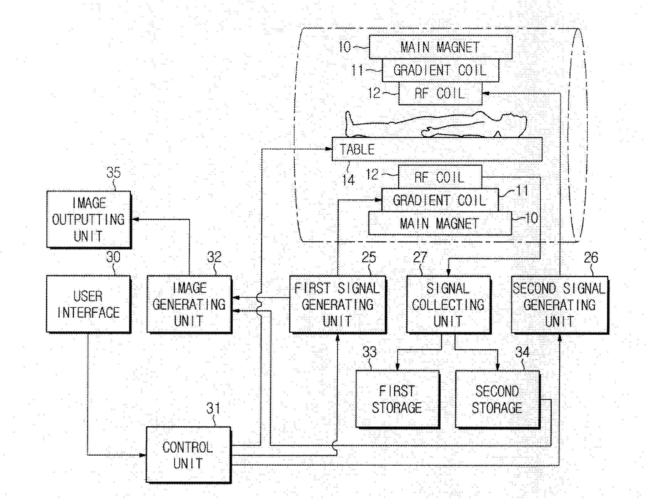
[0050]Hereinafter, aspects of the present invention will be described with reference to the accompanying drawings. In the following description, a detailed explanation of known related functions and constructions may be omitted to avoid unnecessarily obscuring an artisan's appreciation of the subject matter of the present invention with explanations of known functions. This invention may, however, be embodied in many different forms and should not be construed as limited to the exemplary embodiments set forth herein. The same reference numbers are used throughout the drawings to refer to the same or like parts.

[0051]Also, terms described herein, which are defined considering the functions of the present invention, may be implemented differently depending on the user and operator's intentions and practices. Therefore, the terms should be understood on the basis of the disclosure throughout the specification. The principles and features of this invention may be employed in varied and ...


PUM


Abstract

A method and apparatus for reducing scan time, eddy currents and image factors in dynamic magnetic resonance (MR) imaging associated with at least a portion a k-space. The method includes scanning at least a portion of the k-space with an Echo-Planar Imaging (EPI) pulse sequence technique, acquiring a randomly under-sampled k-space; and reconstructing the under-sampled k-space utilizing a constrained reconstruction technique. A dynamic image is constructed of the at least a portion of the k-space based on EPI and the randomly undersampled k-space techniques to each segment of the EPI pulse sequence technique.

Description

CLAIM OF PRIORITY[0001]This application claims priority from U.S. provisional application 61 / 885,117 filed Oct. 1, 2013, the contents of which are incorporated by reference in its entirety.BACKGROUND[0002]1. Field of the Disclosure[0003]The present disclosure relates to Magnetic Resonance Imaging (MRI) methods that provide imaging with reference to time. More particularly, the present disclosure relates to improvements in scan time for MR imaging, in particularly accelerated 4D flow imaging.[0004]2. Description of the Related Art[0005]Medical imaging devices provide images of certain internal portions of a patient's body, and provides a vitally important tool in the detection and treatment of various medical conditions. Various types of medical imaging devices exist and often having respective advantages associated with performing imaging of different areas of the body to be viewed, such as ultrasonic diagnostic equipment, x-ray tomography equipment, magnetic resonance imaging equip...

Claims


Application Information

Patent Timeline
IPC IPC(8): G01R33/561G01R33/385G01R33/30G01R33/48
CPCG01R33/5616G01R33/307G01R33/385G01R33/4818G01R33/4824G01R33/5611G01R33/56316
Inventor BASHA, TAMERNEZAFAT, REZA
Owner BETH ISRAEL DEACONESS MEDICAL CENT INC
Learn More