Method and apparatus for operating a battery arrangement of a motor vehicle

Active Publication Date: 2015-04-09
ROBERT BOSCH GMBH
2 Cites 30 Cited by

AI-Extracted Technical Summary

Problems solved by technology

Below this temperature range, the current losses greatly increase and the maximum output is no longer available.
If the battery is operated outside the temperature range, this can lead to an accelerated aging of the battery and even to the battery becoming damaged.
In this case, the energy consumption that results from heating or cooling of the battery has a negative effect on the range of the motor vehicle.
In the case of...

Method used

[0046]In order to reduce the energy consumption of the motor vehicle 10 (and consequently to increase the range), the energy lost from the vehicle operation and the energy from the environment of the motor vehicle 10, in particular the ambient air, are used in the present invention as further heating/cooling sources. As a consequence, it is possible to reduce the operation of the heating/cooling arrangement 18 to a minimum. In order to minimize the heating/cooling output for the battery arrangement 14 with respect to a simple control of the temperature within a range, it is necessary to know an anticipated temperature progression or rather the heat flowing into or rather out of the battery arrangement 14. It is necessary for this purpose to take into consideration anticipated environmental conditions and/or operating parameters. For this purpose, the device 16 determines by means of the route guidance system 20 a route profile of a route that is to be travelled by the motor vehicle 10. Moreover, the device 16 determines with the aid of the communication network 22 an ambient temperature along the route that is to be travelled by the motor vehicle 10. Furthermore, the device 16 with the aid of the communication network 22 can also determine a temperature development in the target range for the anticipated shut-down time period. This is achieved by way of example by way of contacting a weather forecast service within the communication network 22. In dependence upon these defined environmental conditions and/or operating parameters and using a temperature model of the battery arrangement 14, the device 16 predicts the temperature progression of the battery arrangement 14. With the aid of the predicted temperature progression, the device 16 can control the heating/cooling arrangement 18 in an energy efficient manner. The battery arrangement 14 is only artificially heated or cooled by means of the heating/cooling arrangement 18 if the temperature of the battery arrangement 14 cannot be held within a pre-defined range as a result of the energy lost from the vehicle operation and the energy from the environment of the motor vehicle 10.
[0047]Even in the case of the motor vehicle 10 being connected to the energy supply network 24, the device 16 determines with the aid of the anticipated environmental conditions and/or operating parameters and the predicted temperature progression of the battery arrangement 14 an energy-optimal control of the heating/cooling arrangement 18. If, by way of example by means of the weather forecast service, a very high ambient temperature is predicted for the planned journey on the next day, then the battery arrangement 14 can be pre-cooled by means of the heating/cooling arrangement 18 during the period of time in which the motor vehicle 10 is shut down. Since the motor vehicle 10 is connected to the energy supply network 24, the required energy consumption does not have a negative effect on the range of the motor vehicle 10. On the contrary, it is possible by way of example to forego the cooling of the battery arrangement 14 if the weather forecast service predicts very low ambient temperatures. Consequently, it is not necessary to draw any energy from the energy supply network 24. The energy efficiency of the motor vehicle 10 is thus increased.
[0048]FIG. 2 illustrates a temperature progression 30 as predicted by means of the device 16 for the battery arrangement 14. The time is plotted on the x-axis and the anticipated temperature of the battery arrangement 14 is plotted on the y-axis. As is evident in FIG. 2, a first temperature range 32 and a second temperature range 34 that extends the first temperature range 32 is defined. It is possible within the first temperature range 32 to operate the battery arrangement 14 with small current losses. A rapid ageing and accordingly damage to the battery arrangement 14 is likewise prevented. The second temperature range 34 is dimensioned in such a manner that the battery arrangement 14 can continue to be operated with possibly somewhat higher current losses and whilst maintaining defined conditions. Thus, the battery arrangement 14 is heated or cooled if the battery arrangement 14 is operated over a pre-defined period of time outside the first temperature range 32. Furthermore, the battery arrangement 14 is artificially heated or cooled by means of the heating/cooling arrangement 18 if the battery arrangement 14 is operated outside the first temperature range and moreover if the predicted temperature progression 30 does not indicate that the temperature of the battery arrangement 14 will re-enter the first temperature range 32. In the present embodiment, these two conditions are combined with one another. Thus, the battery arrangement 14 can be artificially heated or cooled if the predicted temperature progression 30 does not indicate a temperature within the first temperature range 32 within a pre-defined period of time. This condition is illustrated by way of example by means of the reference numerals 36 and 38 in FIG. 2. It is evident at the reference numeral 36 that the temperature of the battery arrangement 14 re-enters the first temperature range 32 within a defined time interval. It is thus possible to forego artificially cooling the battery arrangement 14 by means of the heating/cooling arrangement 18. The energy consumption of the motor vehicle 10 is consequently reduced. In the case of the reference numeral 38, the temperature is not expected to re-enter the first temperature range 32. It is therefore necessary to artificially cool the battery arrangement 14 by means of the heating/cooling arrangement 18 in order to prevent damage or rather rapid ageing of the battery arrangement 14. The battery arrangement 14 is likewise artificially heated or ...

Benefits of technology

[0023]The battery arrangement is then only artificially heated or cooled by virtue of this measure if on the basis of the predicted temperature progression of the battery arrangement the temperature is not expected to be within the first temperature range. This in turn reduces the energy consumption of the heating/cooling system and consequently renders it possible to increase the range of the electrically driven motor vehicle.
[0024]In a further embodiment, t...

Abstract

The invention relates to a method (40) for operating a battery arrangement (14) of a motor vehicle (10), in particular a traction battery of the motor vehicle (10), wherein expected environmental conditions and/or use parameters of the motor vehicle (10) are determined (42), wherein an expected withdrawal of energy from an electrical energy store of the battery arrangement (14) is determined (44), wherein a heat loss of the battery arrangement (14) is calculated (46) on the basis of the expected withdrawal of energy, wherein a temperature profile (30) of the battery arrangement (14) is predicted (48) on the basis of the calculated heat loss and the expected environmental conditions and/or use parameters, and wherein a temperature of the battery arrangement (14) is set (54) on the basis of the predicted temperature profile (30).

Application Domain

Technology Topic

Image

  • Method and apparatus for operating a battery arrangement of a motor vehicle
  • Method and apparatus for operating a battery arrangement of a motor vehicle
  • Method and apparatus for operating a battery arrangement of a motor vehicle

Examples

  • Experimental program(1)

Example

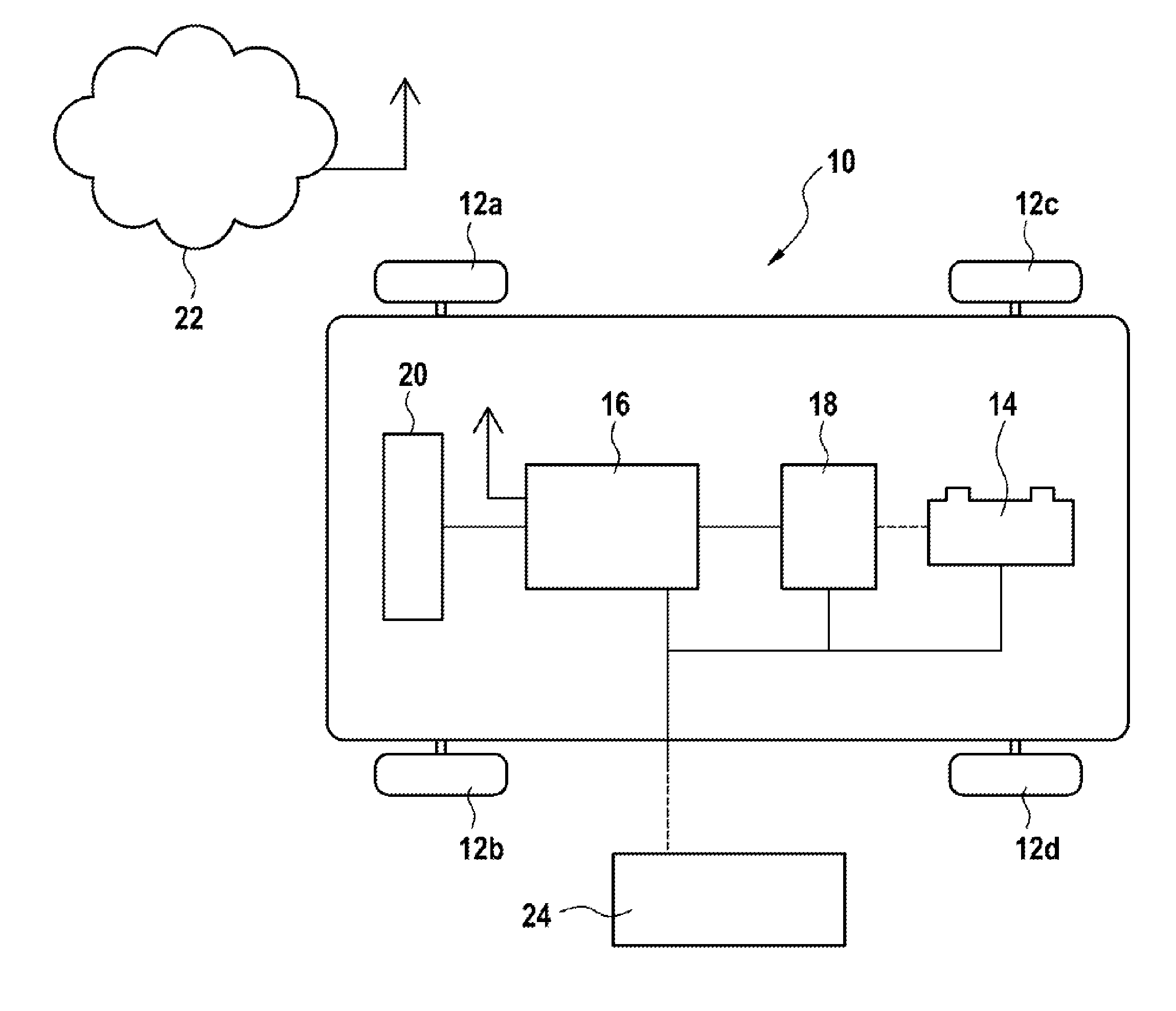
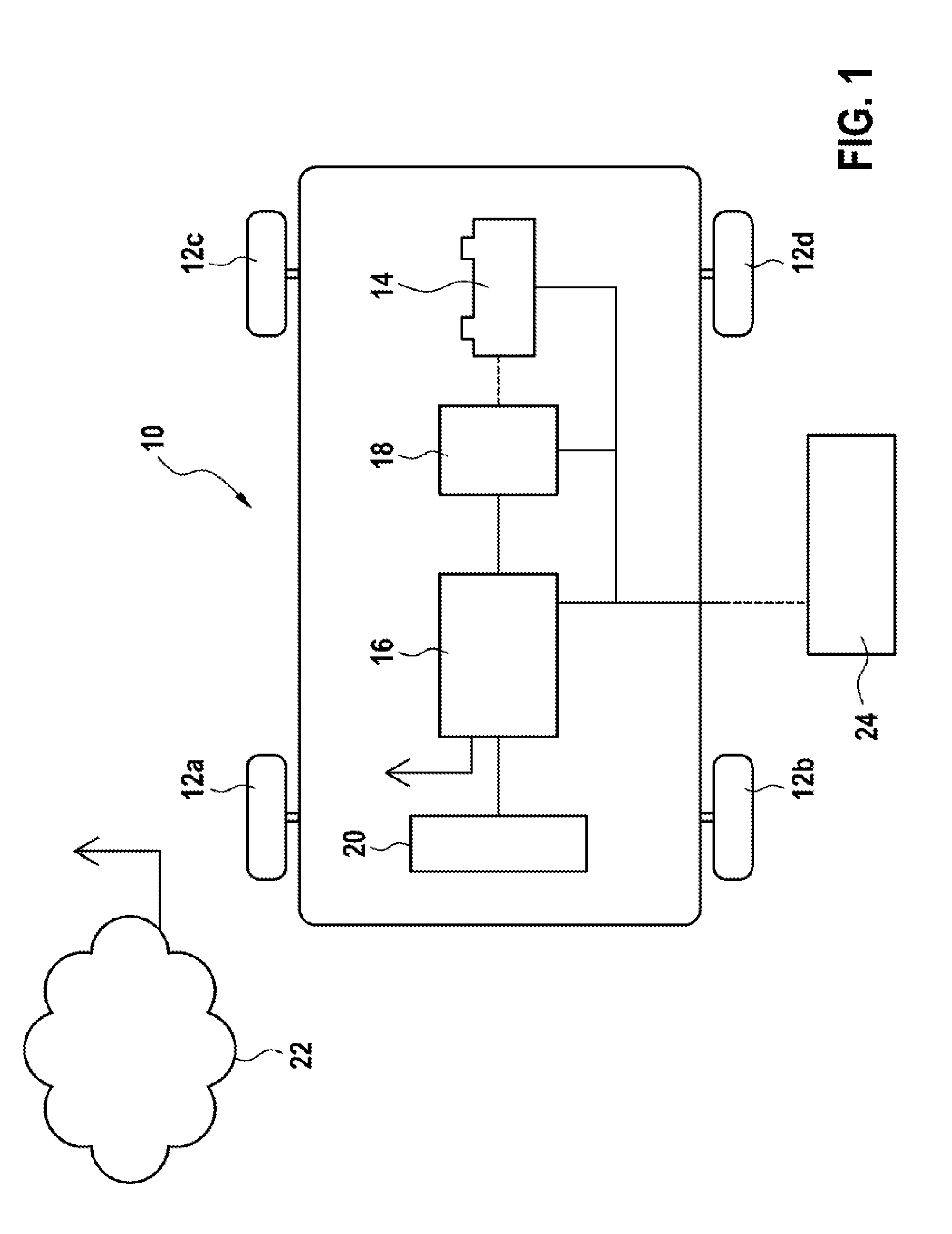
[0043]FIG. 1 illustrates a schematic view of a motor vehicle that is denoted in general by the numeral 10. The motor vehicle 10 comprises an electric drive train for the purpose of providing the drive output and said drive train is not described in detail in FIG. 1. The electric drive train is used for the purpose of driving a defined number of wheels 12 of the motor vehicle 10.
[0044]In an alternative embodiment, the motor vehicle 10 can comprise a conventional drive train having a combustion engine or a hybrid drive train having a combustion motor and an electric machine.
[0045]The motor vehicle 10 comprises a battery arrangement 14 in the present example a traction battery 14 that is used as an electric energy storage device for the electric drive train of the motor vehicle 10. Moreover, the motor vehicle 10 comprises a device 16 in accordance with the invention for the purpose of operating the battery arrangement 14. The device 16 is electrically coupled to a heating/cooling arrangement 18 for the purpose of heating or cooling the battery arrangement 14 and said heating/cooling arrangement is in turn coupled thermally to the battery arrangement 14. Furthermore, the device 16 is electrically connected to a route guidance system 20 and by way of a radio connection to an external communication network 22. Moreover, the motor vehicle 10 can be connected to an external electric energy source 24, in the present case to an external electric energy supply network 24.
[0046]In order to reduce the energy consumption of the motor vehicle 10 (and consequently to increase the range), the energy lost from the vehicle operation and the energy from the environment of the motor vehicle 10, in particular the ambient air, are used in the present invention as further heating/cooling sources. As a consequence, it is possible to reduce the operation of the heating/cooling arrangement 18 to a minimum. In order to minimize the heating/cooling output for the battery arrangement 14 with respect to a simple control of the temperature within a range, it is necessary to know an anticipated temperature progression or rather the heat flowing into or rather out of the battery arrangement 14. It is necessary for this purpose to take into consideration anticipated environmental conditions and/or operating parameters. For this purpose, the device 16 determines by means of the route guidance system 20 a route profile of a route that is to be travelled by the motor vehicle 10. Moreover, the device 16 determines with the aid of the communication network 22 an ambient temperature along the route that is to be travelled by the motor vehicle 10. Furthermore, the device 16 with the aid of the communication network 22 can also determine a temperature development in the target range for the anticipated shut-down time period. This is achieved by way of example by way of contacting a weather forecast service within the communication network 22. In dependence upon these defined environmental conditions and/or operating parameters and using a temperature model of the battery arrangement 14, the device 16 predicts the temperature progression of the battery arrangement 14. With the aid of the predicted temperature progression, the device 16 can control the heating/cooling arrangement 18 in an energy efficient manner. The battery arrangement 14 is only artificially heated or cooled by means of the heating/cooling arrangement 18 if the temperature of the battery arrangement 14 cannot be held within a pre-defined range as a result of the energy lost from the vehicle operation and the energy from the environment of the motor vehicle 10.
[0047]Even in the case of the motor vehicle 10 being connected to the energy supply network 24, the device 16 determines with the aid of the anticipated environmental conditions and/or operating parameters and the predicted temperature progression of the battery arrangement 14 an energy-optimal control of the heating/cooling arrangement 18. If, by way of example by means of the weather forecast service, a very high ambient temperature is predicted for the planned journey on the next day, then the battery arrangement 14 can be pre-cooled by means of the heating/cooling arrangement 18 during the period of time in which the motor vehicle 10 is shut down. Since the motor vehicle 10 is connected to the energy supply network 24, the required energy consumption does not have a negative effect on the range of the motor vehicle 10. On the contrary, it is possible by way of example to forego the cooling of the battery arrangement 14 if the weather forecast service predicts very low ambient temperatures. Consequently, it is not necessary to draw any energy from the energy supply network 24. The energy efficiency of the motor vehicle 10 is thus increased.
[0048]FIG. 2 illustrates a temperature progression 30 as predicted by means of the device 16 for the battery arrangement 14. The time is plotted on the x-axis and the anticipated temperature of the battery arrangement 14 is plotted on the y-axis. As is evident in FIG. 2, a first temperature range 32 and a second temperature range 34 that extends the first temperature range 32 is defined. It is possible within the first temperature range 32 to operate the battery arrangement 14 with small current losses. A rapid ageing and accordingly damage to the battery arrangement 14 is likewise prevented. The second temperature range 34 is dimensioned in such a manner that the battery arrangement 14 can continue to be operated with possibly somewhat higher current losses and whilst maintaining defined conditions. Thus, the battery arrangement 14 is heated or cooled if the battery arrangement 14 is operated over a pre-defined period of time outside the first temperature range 32. Furthermore, the battery arrangement 14 is artificially heated or cooled by means of the heating/cooling arrangement 18 if the battery arrangement 14 is operated outside the first temperature range and moreover if the predicted temperature progression 30 does not indicate that the temperature of the battery arrangement 14 will re-enter the first temperature range 32. In the present embodiment, these two conditions are combined with one another. Thus, the battery arrangement 14 can be artificially heated or cooled if the predicted temperature progression 30 does not indicate a temperature within the first temperature range 32 within a pre-defined period of time. This condition is illustrated by way of example by means of the reference numerals 36 and 38 in FIG. 2. It is evident at the reference numeral 36 that the temperature of the battery arrangement 14 re-enters the first temperature range 32 within a defined time interval. It is thus possible to forego artificially cooling the battery arrangement 14 by means of the heating/cooling arrangement 18. The energy consumption of the motor vehicle 10 is consequently reduced. In the case of the reference numeral 38, the temperature is not expected to re-enter the first temperature range 32. It is therefore necessary to artificially cool the battery arrangement 14 by means of the heating/cooling arrangement 18 in order to prevent damage or rather rapid ageing of the battery arrangement 14. The battery arrangement 14 is likewise artificially heated or cooled if the temperature of the battery arrangement 14 moves outside the second temperature range 34. Furthermore, it is possible also to artificially heat or to cool the battery arrangement 14 if the predicted temperature progression 30 predicts a temperature outside the second temperature range 34. Consequently, the battery arrangement 14 can be pre-conditioned in order to avoid it being very intensively heated or cooled during the subsequent use and consequently to avoid a very high energy consumption.
[0049]If the battery arrangement 14 is operated in a lower temperature range, it is thus possible to provide only a reduced output. It is therefore necessary to limit the power output of the battery arrangement 14. In the case of known methods, the battery is therefore heated to by way of example at least 10° C. (depending upon the battery type) in order to provide the full power immediately. However, this leads to increased energy consumption. In accordance with the invention, the energy consumption of the heating/cooling arrangement 18 is reduced by virtue of the fact that a lower temperature threshold 39 of the first temperature range 32 is set in dependence upon the anticipated environmental conditions and/or operating parameters. If, by way of example as a result of the predicted route and environmental temperatures, it is expected that the power output will be far below a maximal value (for example an urban cycle requires only approx. 20% of the power that is required for a motorway cycle), then the lower temperature threshold 39 is reduced in such a manner that the power requirements are reliably fulfilled. It is consequently no longer necessary to heat the battery arrangement to 10° C. The energy-intensive heating operation is consequently avoided or at least reduced.
[0050]FIG. 3 illustrates an embodiment of a method in accordance with the invention 40 for the purpose of operating the battery arrangement 14 of the motor vehicle 10.
[0051]For this purpose, the anticipated environmental conditions and/or operating parameters of the motor vehicle 10 are initially determined in a first step 42. The route or rather height profile of the route to be travelled by the vehicle 10 is determined by way of example with the aid of the route guidance system 20 or an off-board service within the communication network 22. Temperature data are likewise collected by way of a weather forecast service of the communication network 22 along the route that is to be travelled. Moreover, a driver profile is ascertained that defines by way of example whether the driving style is more sport-like or defensive-like.
[0052]On the basis of the defined environmental conditions and/or operating parameters, an anticipated energy withdrawal from an electric energy storage device of the battery arrangement 14 is determined in step 44. It is thus possible by way of example in the case of great height differences in the route profile and in the case of a sport-like driving style to expect a high energy withdrawal.
[0053]A heat loss in a cooling circuit of the battery arrangement 14 is modeled in step 46 in dependence upon the anticipated energy withdrawal.
[0054]In a further step 48, a temperature model of the battery arrangement 14 is used and said temperature model compares the transmission of heat between the battery arrangement 14 and the vehicle environment of the heat loss in the cooling circuit. Finally, the temperature progression 30 of the battery arrangement 14 is predicted with the aid of the said temperature model and the predicted environmental conditions and/or operating parameters. It is rendered possible by means of the predicted temperature progression 30 to control the heating/cooling arrangement 18 in an energy-optimized manner.
[0055]In a further step 50, a check is performed as to whether the predicted temperature progression 30 moves within the first temperature range 32. If this is the case, it is possible to forego a procedure of artificially heating or cooling the battery arrangement 14. The procedure of regularly determining the predicted temperature progression 30 is then continued with step 42.
[0056]If the predicted temperature progression 30 is not moving within the first temperature range 32, then a check is performed in step 52 as to whether the current temperature of the battery arrangement 14 and the predicted temperature progression 30 are moving within the second temperature range 34.
[0057]If the current temperature or the predicted temperature progression 30 lie outside the second temperature range 34, then the battery arrangement 14 is artificially heated or cooled in step 54 by means of the heating/cooling arrangement 18 in order to set the battery arrangement 14 to a temperature within the first temperature range 32.
[0058]If it is established in step 52 that the current temperature of the battery arrangement 14 or respectively the predicted temperature progression 30 lies within the second temperature range 34, then a check is performed in step 56 regarding the length of the period of time the battery arrangement 14 is being operated outside the first temperature range 32. Furthermore, a check is performed as to whether the predicted temperature progression 30 is indicating a re-entry of the temperature of the battery arrangement 14 into the first temperature range 32. If a re-entry into the first temperature range 32 within a pre-defined period of time is indicated, then it is possible to forego a procedure of artificially heating or cooling the battery arrangement 14 by means of the heating/cooling arrangement 18. The procedure of regularly determining the predicted temperature progression 30 is continued with the step 42. If, however, on the basis of the predicted temperature progression 30 no temperature is to be expected within the first temperature range 32, then it is necessary to artificially heat or cool the battery arrangement 14 in step 54 in order to prevent damage to the battery arrangement 14.
[0059]Following the step 54, the procedure of regularly determining the predicted temperature progression 30 is continued with the aid of step 42.
[0060]It is possible with the aid of the method in accordance with the invention 40 to operate the heating/cooling arrangement 18 in an energy efficient manner. By way of example, it is possible to forego a procedure of actively cooling the battery arrangement 14 if it is concluded from the route progression that the loss of heat will considerably reduce in comparison to the transmission of heat to the vehicle environment (for example imminent change from the motorway to a country road). In a similar manner, a heating operation is not required if because of an imminent incline in the route profile a steep increase in heat loss is to be expected. It is also possible with the aid of the predicted temperature progression 30 to achieve optimizations with respect to energy consumption even for a motor vehicle 10 that is shut down. Thus, for example, it is not necessary to cool the battery arrangement 14 if the journey is about to terminate and the ambient temperature in the target range current or in the future progression lies below the operating temperature and thus contributes to the cooling of the battery arrangement 14. This naturally only applies as long as the temperature of the battery arrangement 14 in the remaining route does not increase to critical values outside the second temperature range 34. However, it is possible to check this condition in advance with the aid of the predicted temperature progression 30.
[0061]If the motor vehicle 10 is connected to the external electric energy source 24, it is thus possible to pre-cool the battery arrangement 14 by way of example to a low temperature within the second temperature range 34 if a high ambient temperature and consequently intense heating by means of the environment is expected for the next journey. As a consequence, it is possible to increase the range of the motor vehicle 10 for the next journey since the energy required for the cooling procedure is drawn from the external electric energy source 24 and not from the battery arrangement 14. This procedure of pre-cooling the battery arrangement 14 can in turn also be optimized with respect to energy by way of the anticipated environment temperature progression. For this purpose, it is possible by way of example to take into consideration temperature minima during the period of time in which the motor vehicle 10 is shut down in order to use the ambient air of the motor vehicle 10 to the best possible extent for cooling the battery arrangement 14. The energy withdrawal from the external electric energy source 24 is consequently minimized.
[0062]Consequently, the energy consumption of the motor vehicle 10 during the driving operation and during the period of time in which the motor vehicle 10 is shut down is minimized by virtue of the present invention.
[0063]Although preferred embodiments of the method in accordance with the invention and the device in accordance with the invention are illustrated, it goes without saying that different variations and modifications can be performed.
[0064]By way of example, the temperature progression 30 can only be determined during a driving operation of the motor vehicle 10.
[0065]Furthermore, the battery arrangement 14 can only be heated or cooled if the temperature is not predicted to be within the first temperature range 32. The period of time in which the battery arrangement 14 is operated outside the first temperature range 32 is not taken into consideration in this exemplary embodiment.

PUM

no PUM

Description & Claims & Application Information

We can also present the details of the Description, Claims and Application information to help users get a comprehensive understanding of the technical details of the patent, such as background art, summary of invention, brief description of drawings, description of embodiments, and other original content. On the other hand, users can also determine the specific scope of protection of the technology through the list of claims; as well as understand the changes in the life cycle of the technology with the presentation of the patent timeline. Login to view more.

Similar technology patents

High grade non- oriented silicon steel and method for manufacturing same

ActiveCN101333620AReduce furnace roll nodulesReduce energy consumptionTemperature control deviceSheet steelElectrical steel
Owner:BAOSHAN IRON & STEEL CO LTD

Classification and recommendation of technical efficacy words

  • Increase range
  • Reduce energy consumption

Containment system for constraining a prosthetic component

InactiveUS7335231B2Eliminate riskIncrease rangeFinger jointsAnkle jointsDislocationFemoral stem
Owner:SMITH & NEPHEW INC

Ocular analyte sensor

InactiveUS6681127B2Increase rangeIncrease sensitivityNanotechMedical devicesInterstitial fluidIntracellular Fluid
Owner:EYESENSE AG

Preparation method of high-strength hydrogel

InactiveCN103739861AThe preparation process takes a short timeReduce energy consumptionPolymer chemistryDouble network
Owner:HENAN POLYTECHNIC UNIV
Why Eureka
Try Eureka