Heart wall tension reduction apparatus

Inactive Publication Date: 2015-04-16
EDWARDS LIFESCIENCES LLC
View PDF2 Cites 5 Cited by
  • Summary
  • Abstract
  • Description
  • Claims
  • Application Information

AI Technical Summary

Benefits of technology

[0010]The present invention pertains to a non-pharmacological, passive apparatus for the treatment of a failing heart. The device is configured to reduce the tension in the heart wall. It is believed to reverse, stop or slow the disease process of a failing heart as it reduces

Problems solved by technology

With damage to the myocardium or chronic volume overload, however, there are increased requirements put on the contracting myocardium to such a level that this compensated state is never achieved and the heart continues to dilate.
The basic problem with a large dilated left ventricle is that there is a significant increase in wall tension and/or stress both during diastolic filling and during systolic contraction.
However, in a failing heart, the ongoing dilatation is greater than the hypertrophy and the result is a rising wall tension requirement for systolic contraction.
This is fe

Method used


Image

  • Heart wall tension reduction apparatus
  • Heart wall tension reduction apparatus
  • Heart wall tension reduction apparatus

Examples


Embodiment Construction

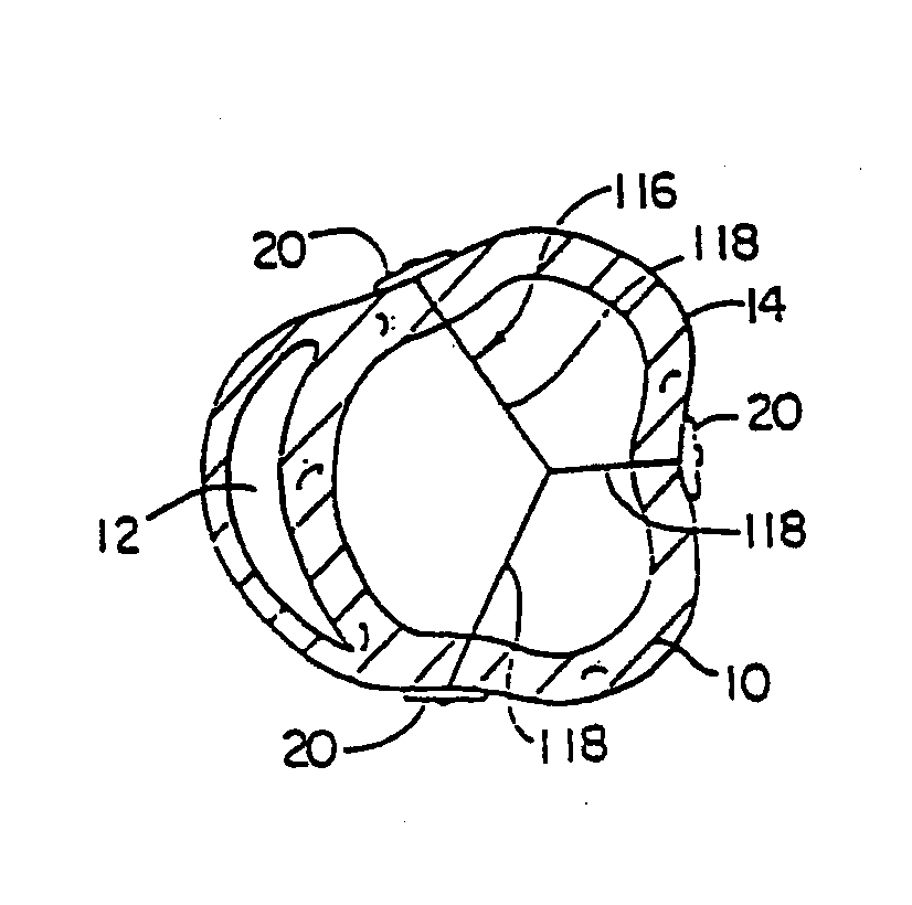
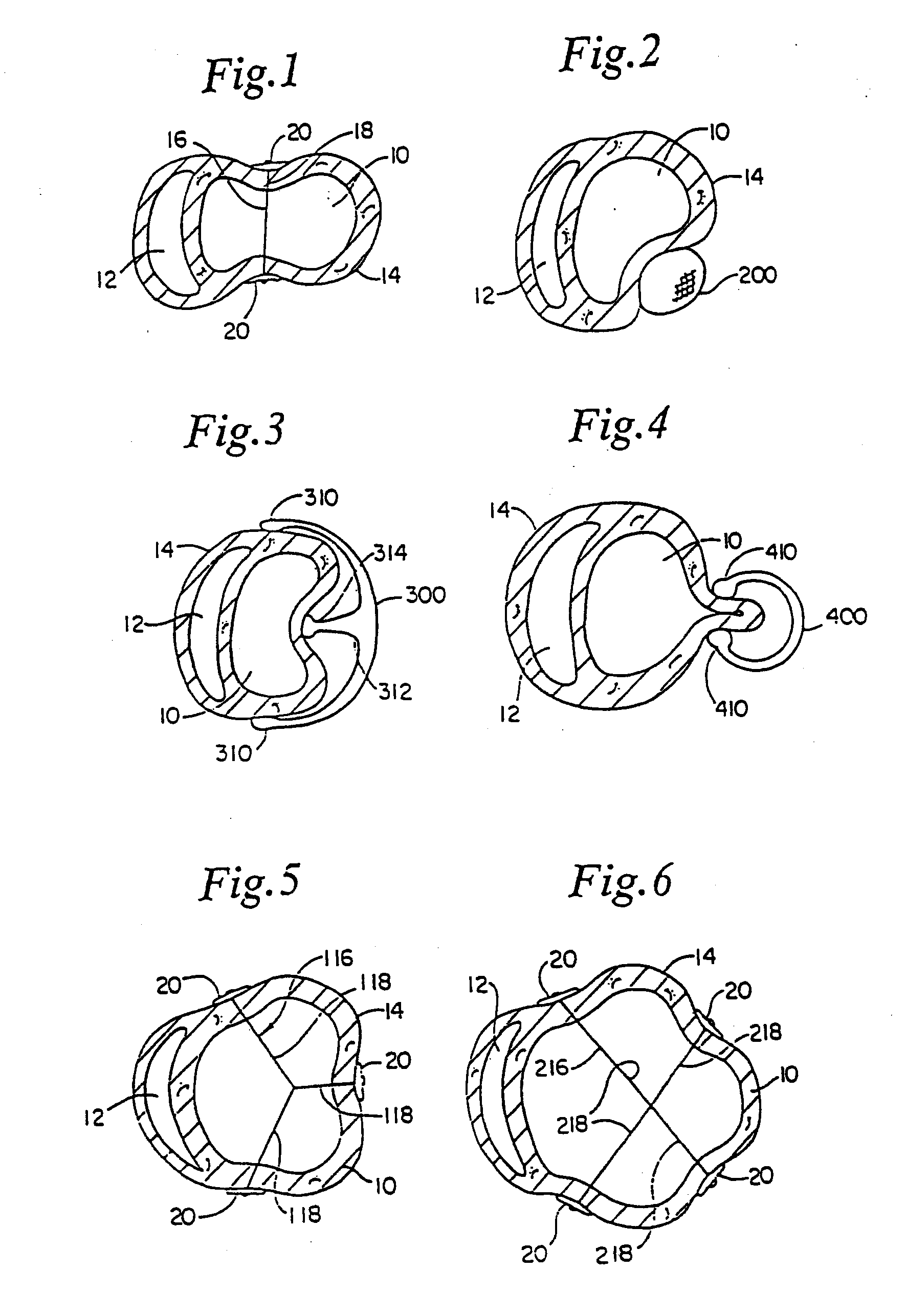
[0032]Referring now to the drawings wherein like reference numerals refer to like elements throughout the several views, FIG. 1 shows a transverse cross-section of a left ventricle 10 and a right ventricle 12 of a human heart 14. Extending through the left ventricle is a splint 16 including a tension member 18 and oppositely disposed anchors 20. Splint 16 as shown in FIG. 1 has been positioned to draw opposite walls of left ventricle 10 toward each other to reduce the “radius” of the left ventricular cross-section or the cross-sectional area thereof to reduce left ventricular wall stresses. It should be understood that although the splint 16 and the alternative devices disclosed herein are described in relation to the left ventricle of a human heart, these devices could also be used to reduce the radius or cross-sectional area of the other chambers of a human heart in transverse or vertical directions, or at an angle between the transverse and vertical.

[0033]FIG. 2 discloses an alte...


PUM


Abstract

An apparatus and method for treatment of a failing heart. In one embodiment, the apparatus and method includes a deploying a tension member for drawing at least two portions of the heart toward each other across a heart chamber.

Description

RELATED APPLICATIONS[0001]This application is a continuation of U.S. application Ser. No. 12 / 314,004, entitled Heart Wall Tension Reduction Apparatus and Method, filed Dec. 2, 2008, which is a continuation of U.S. application Ser. No. 10 / 073,968, entitled Heart Wall Tension Reduction Apparatus and Method, filed Feb. 14, 2002, which is a continuation of U.S. application Ser. No. 09 / 985,361, entitled Heart Wall Tension Reduction Apparatus and Method, filed Nov. 2, 2001, now U.S. Pat. No. 6,589,160, which is a continuation of U.S. application Ser. No. 09 / 697,597, filed Oct. 27, 2000, now U.S. Pat. No, 6,332,864, which is a continuation of application Set No. 09 / 492,777, filed Jan. 28, 2000, now U.S. Pat. No. 6,162,168, which is a continuation of application Ser. No. 08 / 778,277, filed Jan. 2, 1997, now U.S. Pat. No. 6,050,936. The entirety of each of the above applications is incorporated herein by reference.FIELD OF THE INVENTION[0002]The present invention pertains to the field of appa...

Claims


Application Information

Patent Timeline
IPC IPC(8): A61F2/24
CPCA61F2/2481A61B17/12A61B17/1227A61B2017/0417A61F2/2487
Inventor SCHWEICH, JR., CYRIL J.MORTIER, TODD J.
Owner EDWARDS LIFESCIENCES LLC
Why Eureka
Try Eureka