Dry powder inhaler (DPI) designs for producing aerosols with high fine particle fractions
a technology of aerosol and fine particle fraction, which is applied in the field of inhalation therapy, can solve the problems of significant device and extrathoracic drug deposition, inability to generate sufficient flow from patients, and low quality and performance of these aerosols, and achieves the effect of high aerosol dispersibility, improved performance of cc1-3d, and improved placement of holes
- Summary
- Abstract
- Description
- Claims
- Application Information
AI Technical Summary
Benefits of technology
Problems solved by technology
Method used
Image
Examples
example 1
Improvement of Existing Device with a 3-D Array of Rods
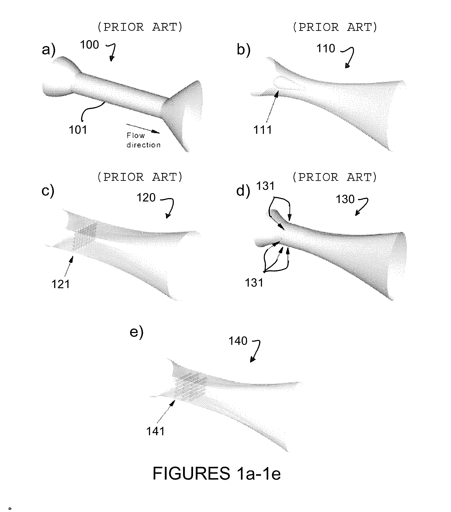
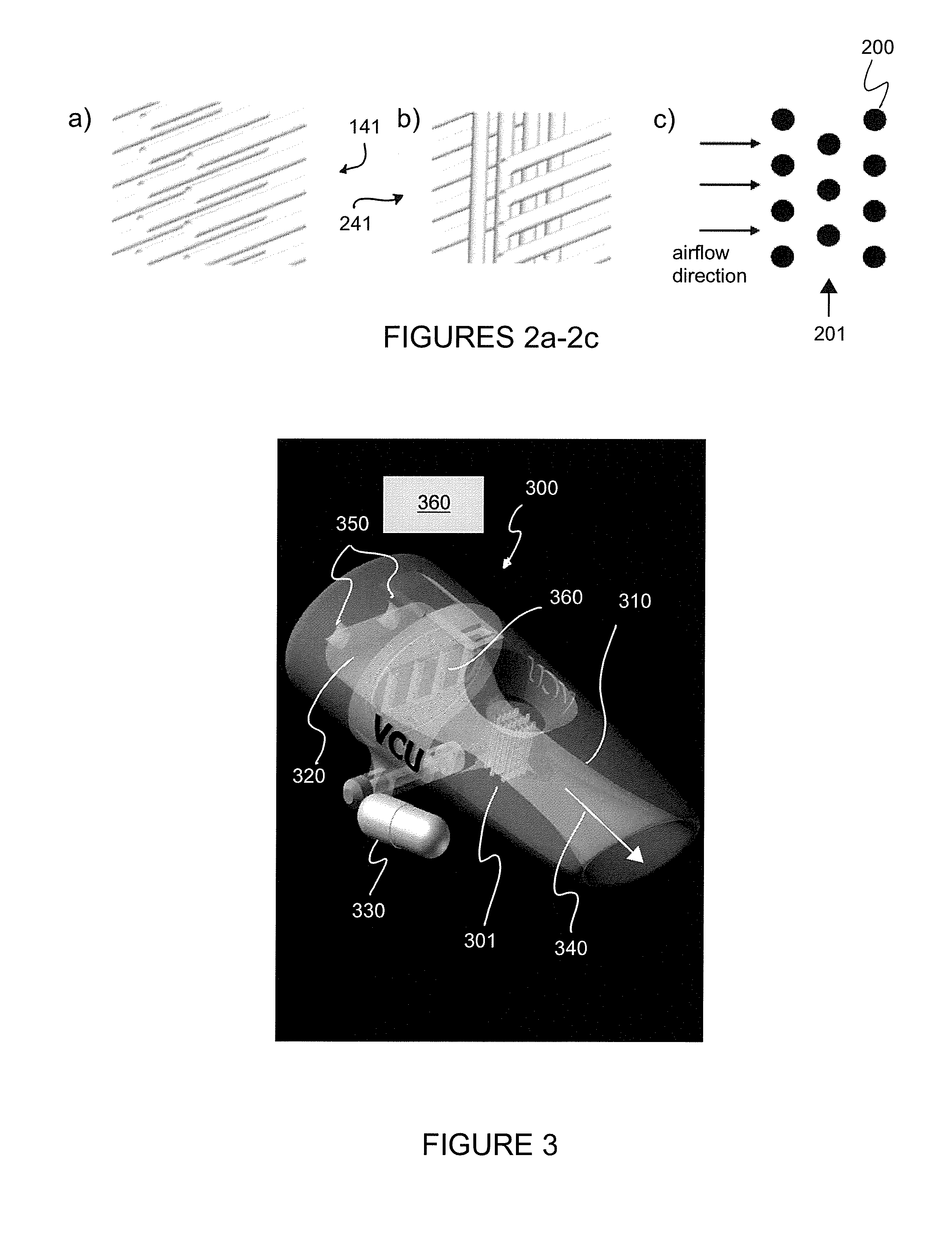
[0067]Table 1 shows the aerosolization characteristics of a proprietary spray dried submicrometer powder drug formulation in both active and passive DPIs (Son et al., 2012). The aerosolization characterization results indicated the relative efficiency of the DPIs to disperse the formulation to primary drug particles for inhalation. State-of-the-art active DPIs are considered first and produced very low FPF1 μm (less than 10%) for this submicrometer formulation. State-of-the art passive DPIs improved dispersion using the Aerolizer and HandiHaler producing FPF1 μm of the emitted dose (ED) of 28.3 and 19.5%, respectively. In the final row of the table, the flow passage of the HandiHaler device (FIG. 1a) was replaced with a flow passage containing a 3D rod array of rods (FIG. 1e) as disclosed in this invention. The HandiHaler with the modified 3D array results in a 2× increase in FPF1 μm and a significant reduction in drug MMAD (Tab...
example 2
Correlation of FPF with Turbulence (Longest et al., 2013)
[0068]It is known that turbulence in the inhaler increases the deaggregation of particles in some cases (Voss and Finlay 2002). However, previous correlations between FPF and turbulence level have been weak. A new parameter is proposed for the design of DPIs to quantify the form of turbulence most responsible for aerosol breakup in the inhaler. The 3D rod array inhaler will be shown to optimize this form of turbulence.
[0069]In turbulence, the specific dissipation rate is typically defined as (Wilcox 1998)
ω=k1 / 2Cμ1 / 4(1)
where k is the turbulent kinetic energy [m2 / s2], Cμ is a constant equal to 0.09, and l is the characteristic eddy length scale [m]. The ω parameter captures both kinetic energy available for breakup along with eddy length scale, with smaller eddies being more effective at breaking up small aggregates and increasing FPF. For an inhaler geometry, the volume-averaged specific dissipation is calculated as
ϖ=1V∫VωCVV[1...
example 3
Inhaler Performance at a Constant Flow Rate
[0072]One method to compare inhaler performance on a consistent basis is to consider all devices of interest at the same flow rate. The existing flow passage of the HandiHaler (small diameter or constricted tube) was considered along with turbulence inducing flow passages containing an impaction surface (FIG. 1b), 2D mesh (FIG. 1c), jets (FIG. 1d), and 3D array of rods (FIG. 1e). All systems were operated at 45 LPM to aerosolize a proprietary spray dried submicrometer drug powder formulation. In vitro experiments of exiting drug aerosol size were conducted based on impactor testing and drug quantification using high performance liquid chromatography (HPLC). In vitro results along with CFD predictions of NDSD are reported in Table 2. Based on these results at a constant flow rate, the 3D rod array maximizes FPF1 and FPF5 μm for the drug aerosol. The 3D rod array was also the only inhaler to generate a submicrometer aerosol based on geometric...
PUM
| Property | Measurement | Unit |
|---|---|---|
| inclined angle | aaaaa | aaaaa |
| aerodynamic diameter | aaaaa | aaaaa |
| aerodynamic diameters | aaaaa | aaaaa |
Abstract
Description
Claims
Application Information
 - R&D
- Intellectual Property
- Life Sciences
- Materials
- Tech Scout
- Unparalleled Data Quality
- Higher Quality Content
- 60% Fewer Hallucinations
Browse by: Latest US Patents, China's latest patents, Technical Efficacy Thesaurus, Application Domain, Technology Topic, Popular Technical Reports.
© 2025 PatSnap. All rights reserved.Legal|Privacy policy|Modern Slavery Act Transparency Statement|Sitemap|About US| Contact US: help@patsnap.com


