Hydraulic borehole mining system and method

a hydraulic and borehole technology, applied in the direction of borehole/well accessories, fluid removal, construction, etc., can solve the problems of inability to reduce the operating footprint and personnel, high energy requirements, and inability to reduce the pressure or fluid loss at the connection, so as to reduce equipment, energy and cost, and maximize the fluid flow efficiency

Inactive Publication Date: 2015-04-23
ISLANDER
View PDF0 Cites 9 Cited by
  • Summary
  • Abstract
  • Description
  • Claims
  • Application Information

AI Technical Summary

Benefits of technology

[0030]All of the elements of this mining system are designed to maximize fluid flow efficiency both down and up the wellbore. This fluid circulation with the air supported laminar hydraulic jet and the return to surface using differential pressure allows a significant reduction in equipment, energy and costs from any past versions of hydraulic borehole mining systems. Minimization of economics and reduction of the operating footprint and personnel prove to define commercial economics in multiple target ore types.

Problems solved by technology

However, as a stand-alone method of lifting, the energy requirements are very high and require that a very high ratio of fluid and pressure be circulated to the bottom of the well bore to educt the disaggregated resource material back to the surface.
A pressure or fluid loss at a connection is intolerable due to the safety risk at high pressures and the need to control jet volumes and consistent delivery pressure at the outlet.

Method used


Image

  • Hydraulic borehole mining system and method
  • Hydraulic borehole mining system and method
  • Hydraulic borehole mining system and method

Examples


Embodiment Construction

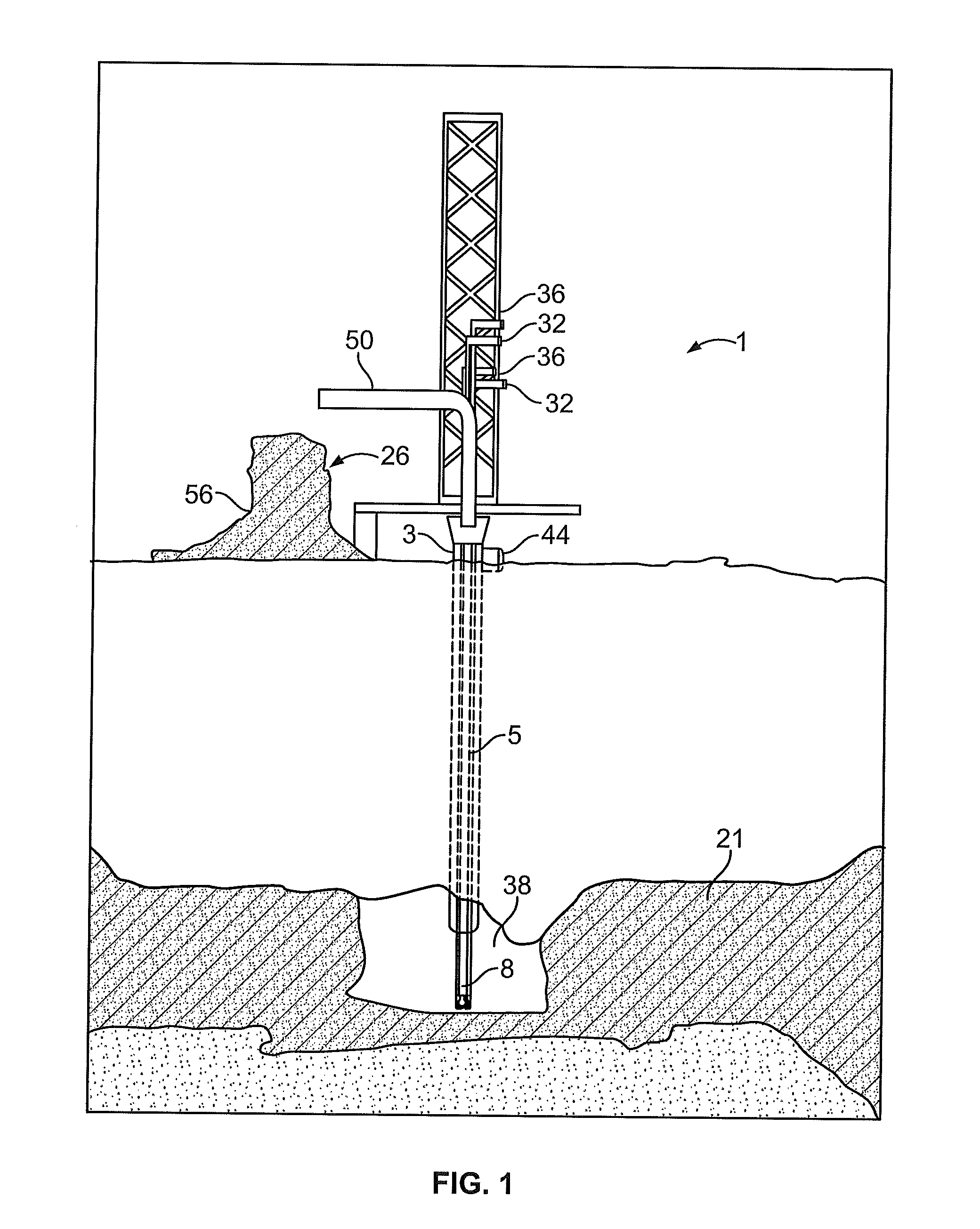
[0043]Referring now to FIG. 1, a system and a process of hydraulic borehole mining for a subterranean resource in accordance with the present invention is described in detail. A rig shown generally at 1 is brought to the site, situated at a preferred location at the site, and operated to drill a well (or wellbore, as the term is used in the art) to the top of the resource body. The wellbore may be drilled at any angle from vertical to horizontal depending upon the geotechnical mining conditions down-hole and the structure of the ore body itself. A casing string 3, if required, is then run into the initial bore and cemented into position to give strength to the wellbore. A conventional drill string is then fed into the casing string, and a pilot hole is drilled through the resource body. The conventional drilling string (not shown) is thereafter removed from the hole.

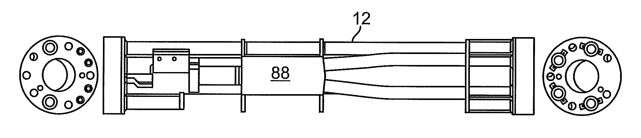
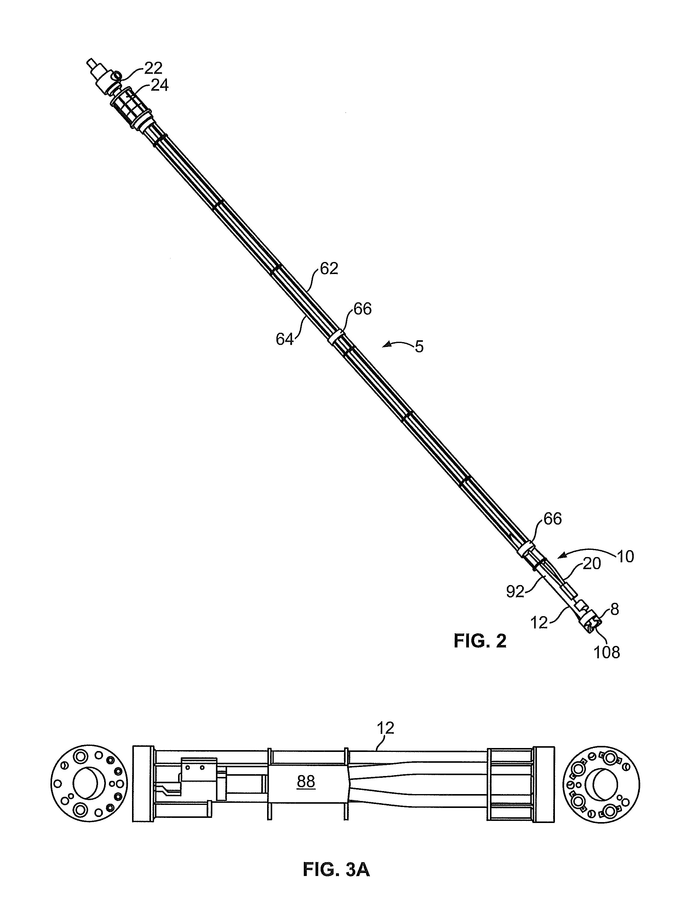
[0044]Referring now to FIGS. 2 and 6(a)-(b), a mining string 5 is illustrated in greater detail. The mining string is ...


PUM


Abstract

A hydraulic borehole mining system controlled and operated above-ground includes a high-pressure cutting nozzle that is delivered to an underground resource body through a relatively small diameter borehole. A series of water and air fluid streams at various pressures are delivered to the resource body, and the target resource is disaggregated and/or fluidized and conveyed back to surface via the hydraulic borehole mining pipe which serves as the conveyor of the system. The mining pipe is used to transport a high-pressure stream of combined air and water fluids that have been directed and aligned into laminar flow to a focused water jet cutting head. The central bore of the mining pipe brings the slurrified resource to the surface. The mining pipe transports the slurry via hydraulic airlift, fluid eduction or both.

Description

CROSS-REFERENCE TO A RELATED APPLICATION[0001]This application claims the benefit of U.S. provisional patent application Ser. No. 61 / 891,674, filed on Oct. 16, 2013, entitled “HYDRAULIC BOREHOLE MINING SYSTEM AND METHOD,” the entire disclosure of which is incorporated herein by reference.FIELD OF THE INVENTION[0002]The present application relates to the field of subterranean hydraulic borehole mining. More specifically, the present invention relates to a new and novel high pressure system and method to perform economic, high production, continuous commercial mining by hydraulic borehole mining within a target ore body either in fully submerged conditions below the water table or at full atmospheric conditions.BACKGROUND OF THE INVENTION[0003]In situ hydraulic borehole mining equipment and techniques have been patented in the past for applications that include the mining of uranium, phosphate and heavy oil resource bodies, such as U.S. Pat. No. 4,915,452 issued to Dibble; U.S. Pat. N...

Claims


Application Information

Patent Timeline
Patent Type & Authority Applications(United States)
IPC IPC(8): E21B43/29E21B7/18E21B21/12E21B21/01E21B41/00
CPCE21B43/29E21B21/01E21B7/18E21B21/12E21B41/0078
Inventor KINLEY, COLIN B.MAC EWEN, ANDREW
Owner ISLANDER
Why Eureka
Try Eureka