
Stereo projection apparatus and stereo projection system with low throw ratio and high light efficiency

a projection apparatus and high light efficiency technology, applied in the field of stereo projection technology, can solve the problems of long light path, large-sized optical devices, and difficult overlapping of two beams of light, and achieve the effects of low throw ratio, high light efficiency, and low throw ratio

Active Publication Date: 2015-04-23
SHENZHEN TIME WAYING TECH
View PDF3 Cites 27 Cited by
  • Summary
  • Abstract
  • Description
  • Claims
  • Application Information

AI Technical Summary

Benefits of technology

The present invention is about a new type of projection system that can show 3D images. It is designed to be smaller and more efficient than existing systems. The new system uses a special device called a polarized beam splitter to split the light into three parts, which helps to reduce the size of the whole system and makes it easier for the different light beams to overlap. The system also uses a special device called a twisted liquid crystal device to rotate the direction of the polarized light, which provides better efficiency and controls how different colors of light are affected by the system. Overall, this new invention is smaller, more efficient, and easier to use for showing 3D images.

Problems solved by technology

This technology results in a long light path and hence requires large-sized optical devices.
When a low throw ratio projector is used, each optical device needs to have a very large size, and overlapping of the two beams of light also becomes very difficult.
In addition, there are difficulties in device manufacture and assembly as well as mass production of the projector.

Method used


Image

  • Stereo projection apparatus and stereo projection system  with low throw ratio and high light efficiency
  • Stereo projection apparatus and stereo projection system  with low throw ratio and high light efficiency
  • Stereo projection apparatus and stereo projection system  with low throw ratio and high light efficiency

Examples


first embodiment

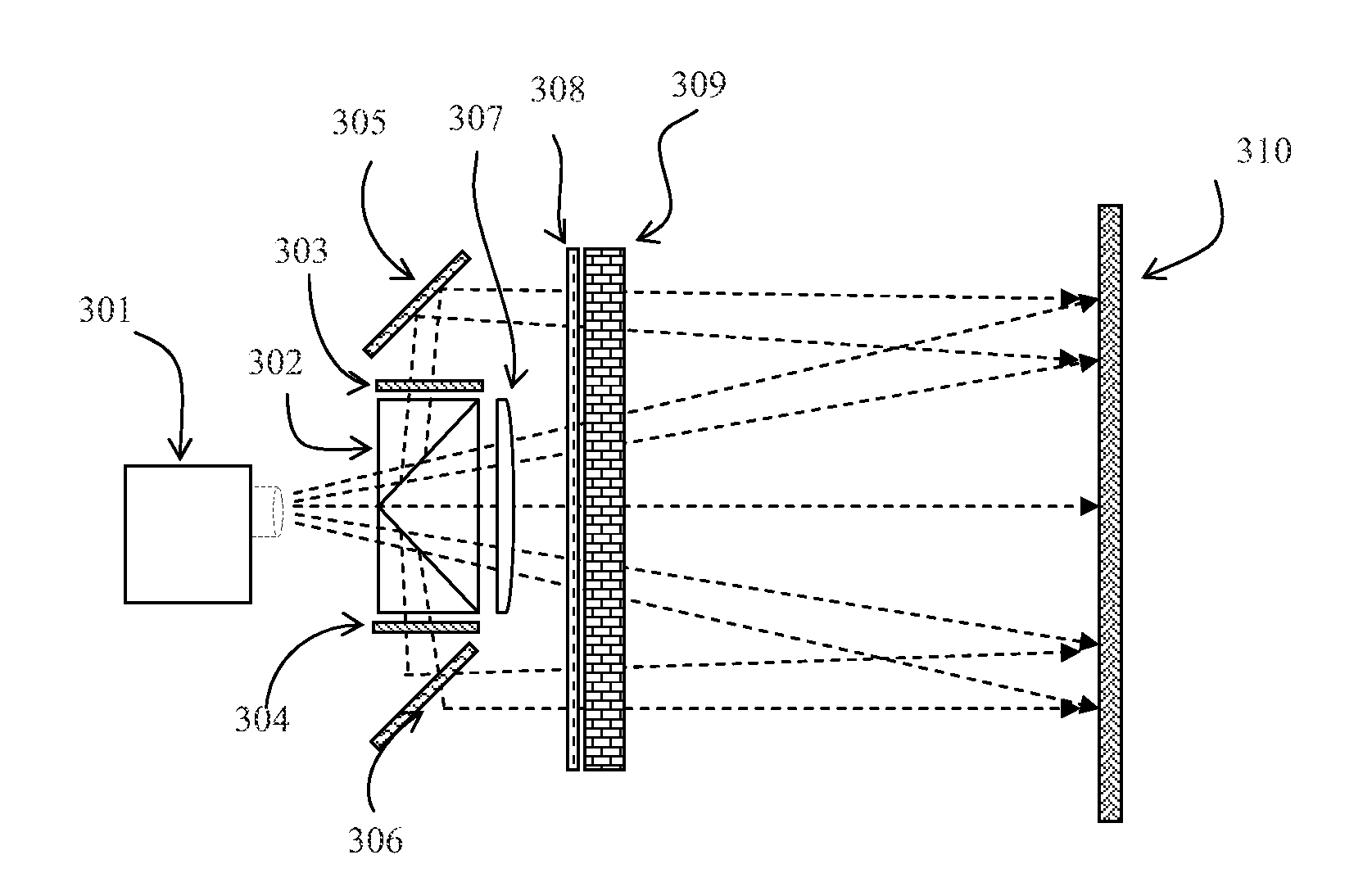
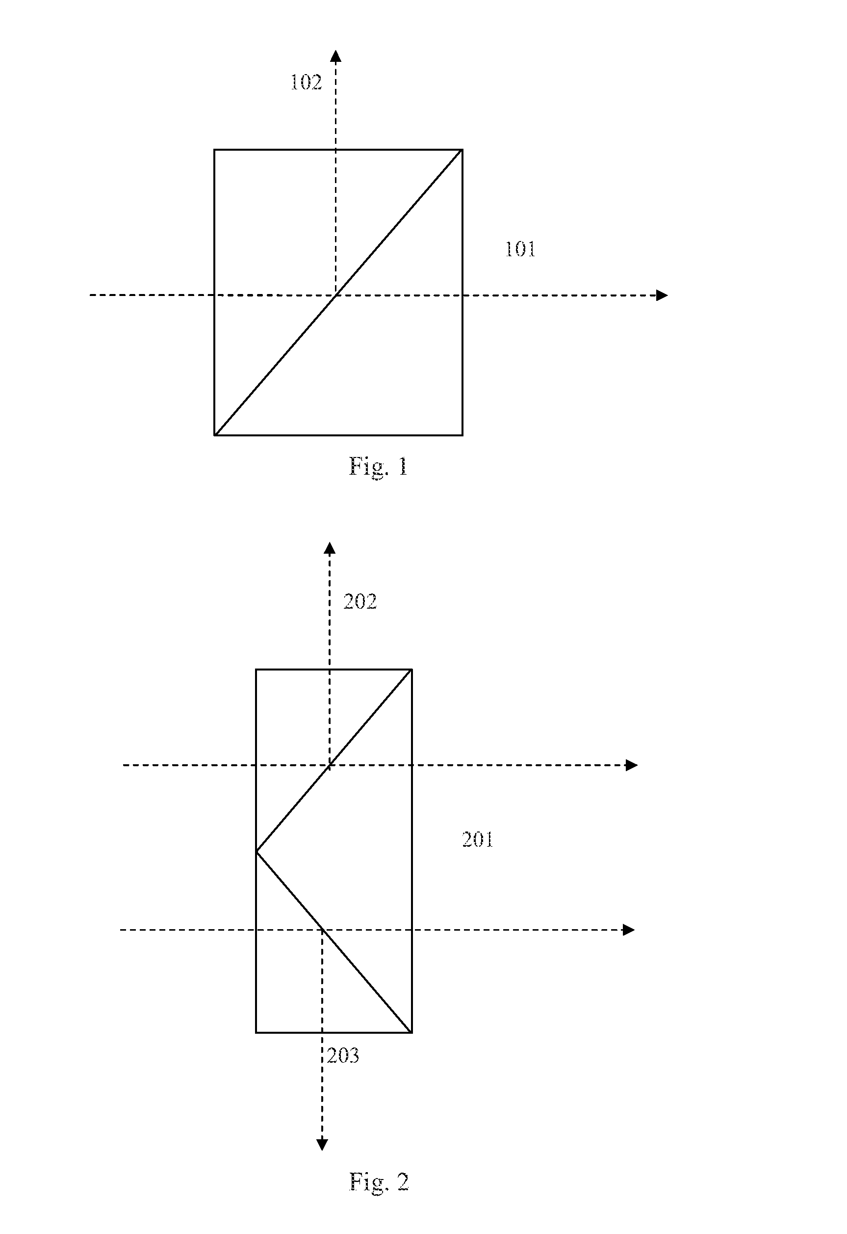
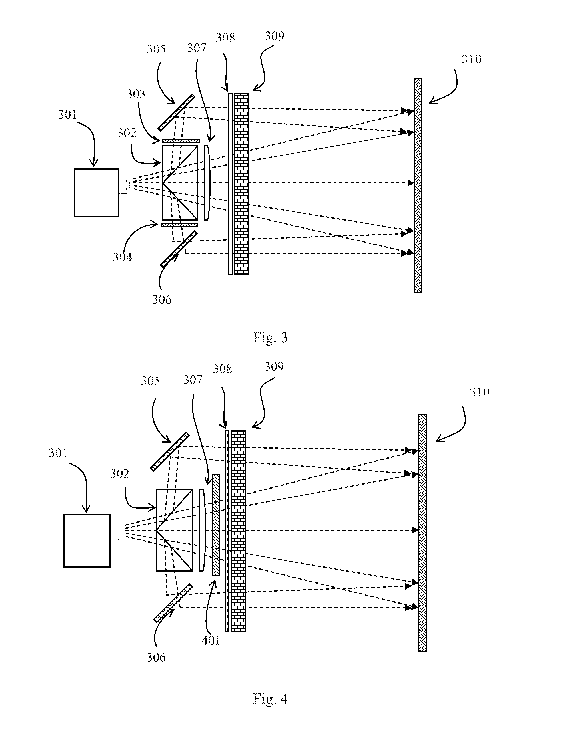
[0028]As shown in FIG. 3, the stereo projection apparatus with low throw ratio and high light efficiency of the present invention includes a polarized beam splitter assembly 302, light path direction adjustment assemblies 305 and 306, polarization state transforming assemblies 303 and 304, a light beam size adjustment assembly 307, and a light modulator 309. The polarized beam splitter assembly 302 is used to split an incident light from a lens of a projector 301 into a transmitted light beam 201, a first reflective light beam 202 and a second reflective light beam 203. The transmitted light beam has a P-polarization state, and the two reflective light beams have a S-polarization state. The transmitted light beam and reflective light beams are collectively referred to as polarized lights. The polarized beam splitter assembly 302 splits the light beam of the projector 301 into the transmitted light beam 201, the first reflective light beam 202 and the second reflective light beam 203...

second embodiment

[0032]In a second embodiment, as shown in FIG. 4, the twisted liquid crystal device is disposed after the polarized beam splitter prism set to adjust the transmitted light beam to have a consistent polarization state with the reflective light beams.

third embodiment

[0033]In a third embodiment, as shown in FIG. 5, there are two twisted liquid crystal devices disposed in the reflective light beams. The two twisted liquid crystal devices are respectively disposed between the two reflective mirrors and the linear polarizer 308 to adjust the reflective light beams to have a consistent polarization state with the transmitted light beams.

[0034]In combination with the various embodiments above, the twisted liquid crystal device may be a traditional glass-substrate-based liquid crystal device, which consists of a glass substrate, transparent conductor layer, alignment layer, spacer, sealing material, liquid crystal material. The twisted liquid crystal device may also be a flexible-plastic-substrate-based liquid crystal device, which consists of a plastic substrate, transparent conductor layer, alignment layer, spacer, sealing material, liquid crystal material. The twisted liquid crystal device may also be a macromolecule liquid crystal film based on po...


PUM


Abstract

A stereo projection apparatus includes a polarized beam splitter assembly for splitting a projecting light beam into a transmitted light beam, a first reflective light beam and a second reflective light beam; a polarization state transforming assembly for adjusting the polarization state of the transmitted light beam or the polarization state of the first reflective light beam and second reflective beam; a light path direction adjustment assembly for adjusting a travel direction of the transmitted light beam or a travel direction of the first reflective light beam and the second reflective light beam; a light beam size adjustment assembly for adjusting a coverage range of the transmitted light beam or a coverage range of the first reflective light beam and the second reflective light beam; and a light modulator for modulating the adjusted transmitted light beam, first reflective light beam and second reflective light beam to left-circularly polarized light and right-circularly polarized light in accordance with a frame sequence. The stereo projection apparatus can effectively reduce the optical path difference between the reflective light and transmitted light, thereby significantly reducing the size of the entire device and making overlapping of the various light beams easier.

Description

FIELD[0001]The present invention relates to stereo projection technology and, more particularly, to a stereo projection apparatus and stereo projection system with low throw ratio and high light efficiency.BACKGROUND[0002]In Chinese Patent No. 201220746320.8, entitled “high light efficiency light modulation apparatus and high light efficiency stereo projection system”, a large-sized polarized beam splitter device is required to split an incident light into a transmitted light beam and a reflective light beam and then adjust the polarization state of the light beams to make the two light beams overlap on a metal screen. This technology results in a long light path and hence requires large-sized optical devices. When a low throw ratio projector is used, each optical device needs to have a very large size, and overlapping of the two beams of light also becomes very difficult. In addition, there are difficulties in device manufacture and assembly as well as mass production of the projec...

Claims


Application Information

Patent Timeline
IPC IPC(8): G02B27/26H04N13/04G02B30/25G03B35/26H04N13/363H04N13/39
CPCG02B27/26G02B5/3016G02B27/285H04N13/0459H04N13/363H04N13/337G02B30/25H04N13/39
Inventor LI, YANLONGDENG, XIANJUNWANG, YETONG
Owner SHENZHEN TIME WAYING TECH
Learn More