Hybrid rope or hybrid strand

a hybrid rope and rope technology, applied in the field of hybrid ropes, can solve the problems of excessive weight of cables with metallic cores and limited payloads, and achieve the effects of low weight and volume, high breaking load level, and sufficient corrosion resistan

Active Publication Date: 2015-04-30
BRIDON INT LTD +1
View PDF16 Cites 20 Cited by
  • Summary
  • Abstract
  • Description
  • Claims
  • Application Information

AI Technical Summary

Benefits of technology

[0010]It is another object of the present invention to devise a hybrid rope having low weight and volume in comparison with their strength and the method to produce thereof.
[0011]It is still another object of the present invention to devise a hybri

Problems solved by technology

The cable with metallic core has a disadvantage of being exceedingly heavy in long lengths.
This is because, during such use, the weight of

Method used


Image

  • Hybrid rope or hybrid strand
  • Hybrid rope or hybrid strand
  • Hybrid rope or hybrid strand

Examples


first embodiment

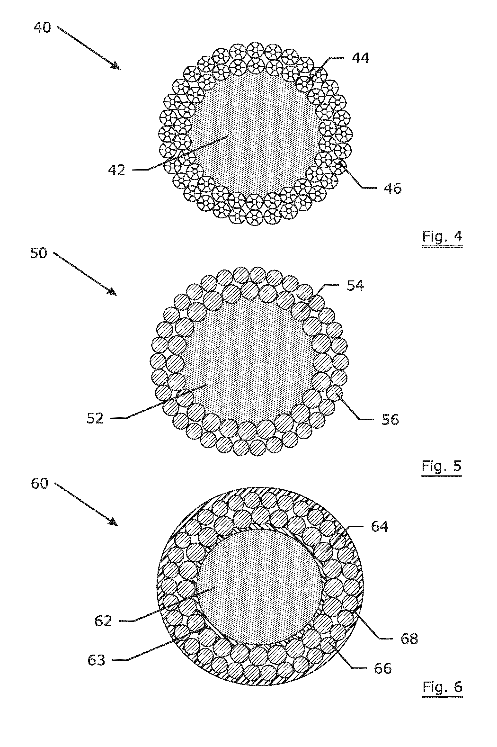
[0050]FIG. 4 is a cross-section of an invention hybrid rope according to the invention. The invention hybrid rope 40 comprises a fiber core 42, first metallic wirelike members 44 and second metallic wirelike members 46. The hybrid rope 40 may have a diameter ranging from 10 mm to 400 mm. The hybrid rope 40 as illustrated in FIG. 4 has a “32×7c+26×7c-FFC SsZs, SzZz or ZzSz” rope construction. The term “32×7c+26×7c-FFC SsZs” refers to a rope design with the second metallic layer (most outside layer) having 32 strands (i.e. second metallic wirelike members 46) with a rotating direction of “S”, wherein each strand contains 7 compacted filaments with a rotating direction of “s”, the first metallic layer having 26 strands (i.e. first metallic wirelike members 44) with a rotating direction of “Z”, wherein each strand contains 7 compacted filaments with a rotating direction of “s”, and a fiber core (abbreviated as FC). The rope construction as shown in table 1 are denoted in a similar way. ...

third embodiment

[0056]FIG. 6 is a cross-section of an invention hybrid rope according to the invention. As an example, the illustrated hybrid rope has a construction of “34+24-FFC SZ”. The invention hybrid rope 60 comprises a fiber core 62, a extruded thermoplastic layer 63 around the core 62, first metallic wirelike members 64, second metallic wirelike members 66 and a thermoplastic protection layer 68.

[0057]As an example, a coating of a plastomer EXACT™ 0230 is extruded on the core of the rope using a Collin™ 45 mm single screw extruder. Polyethylene (PE) is extruded on the entire rope as a protection layer.

[0058]It goes without saying that either only an extruded coating on the core (and no extruded layer on the entire rope) or merely an extruded layer on the entire rope (and no extruded coatings on the core) are also within the scope of the invention. In addition, an additional coating / extruded layer can be added in between the two metallic layers to avoid fretting in between the metallic layer...


PUM

PropertyMeasurementUnit
Angleaaaaaaaaaa
Angleaaaaaaaaaa
Diameteraaaaaaaaaa

Abstract

A hybrid rope (40) or a hybrid strand (50) comprising a core element (42, 52), a first (44, 54) and a second (46, 56) metallic closed layer surrounding said core element (42, 52). The core element (42, 52) includes a bundle of synthetic yarns. The first metallic closed layer (44, 54) includes a plurality of first strands of wires helically twisted together with the core element (42, 52) in a first direction. The second metallic closed layer (46, 56) includes a plurality of second wires or strands helically twisted together with said core element (42, 52) and said first metallic closed layer (44, 54) in a second direction. The cross-sectional area of the core element (42, 52) is larger than the total cross-sectional area of the first (44, 54) and second (46, 56) metallic closed layers. A corresponding method of producing such a hybrid rope or hybrid strand is also disclosed.

Description

TECHNICAL FIELD[0001]The invention relates to a hybrid rope comprising a core element and outer metallic closed layers, to the termination of the rope and to a method of producing such a hybrid rope.BACKGROUND ART[0002]Conventional wire ropes and cables normally feature a metallic core surrounded by an outer layer of helically laid steel wire or wire strands. The cable with metallic core has a disadvantage of being exceedingly heavy in long lengths.[0003]Therefore, ropes with a core of natural or synthetic fibers twisted together with metallic wire strands, i. e. so called hybrid ropes, are introduced to impart various characteristics to the ropes depending on the type of natural or synthetic fibers used.[0004]An advantage of a hybrid rope in view of a fully steel rope is the lower weight of the rope and improved performance like e.g. tension and bending fatigue.[0005]The advantage of the hybrid rope in view of a fully synthetic rope, e.g. nylon, is that the hybrid rope is highly re...

Claims


Application Information

Patent Timeline
IPC IPC(8): D07B1/06D07B5/00D07B7/16D07B1/16D07B3/00
CPCD07B1/0673D07B1/162D07B5/00D07B7/16D07B3/00D07B2401/2085D07B1/0686D07B1/0693D07B1/165D07B2201/1016D07B2201/102D07B2201/1036D07B2201/1064D07B2201/1068D07B2201/1072D07B2201/108D07B2201/2019D07B2201/202D07B2201/2023D07B2201/2027D07B2201/203D07B2201/204D07B2201/2051D07B2201/2055D07B2201/2057D07B2201/2065D07B2201/2068D07B2201/2074D07B2201/2087D07B2201/209D07B2205/2014D07B2205/205D07B2205/2096D07B2401/2055D07B2501/2007D07B2501/2015D07B2501/2061F16G11/042D07B2801/12D07B2801/24D07B2801/14D07B1/06
Inventor AMILS, XAVIERDURMUS, BESTESMEETS, PAULUS JOHANNES HYACINTHUS MARIE
Owner BRIDON INT LTD
Why Eureka
Try Eureka