
Backlight unit and liquid crystal display using the same

a backlight unit and liquid crystal display technology, applied in static indicating devices, instruments, optics, etc., can solve the problems of inability to perform backlight scanning drives and local dimming drives, large size of fluorescent lamps, and high power consumption, so as to reduce power consumption, reduce noise, and reduce the effect of electromagnetic interferen

Active Publication Date: 2015-04-30
LG DISPLAY CO LTD
View PDF12 Cites 41 Cited by
  • Summary
  • Abstract
  • Description
  • Claims
  • Application Information

AI Technical Summary

Benefits of technology

This patent aims to provide a backlight unit and liquid crystal display that can perform both backlight scanning and local dimming while reducing power consumption, electromagnetic interference, heat generation, noise, and wavy noise.

Problems solved by technology

However, the fluorescent lamps have a relatively large size, high power consumption, and low brightness.
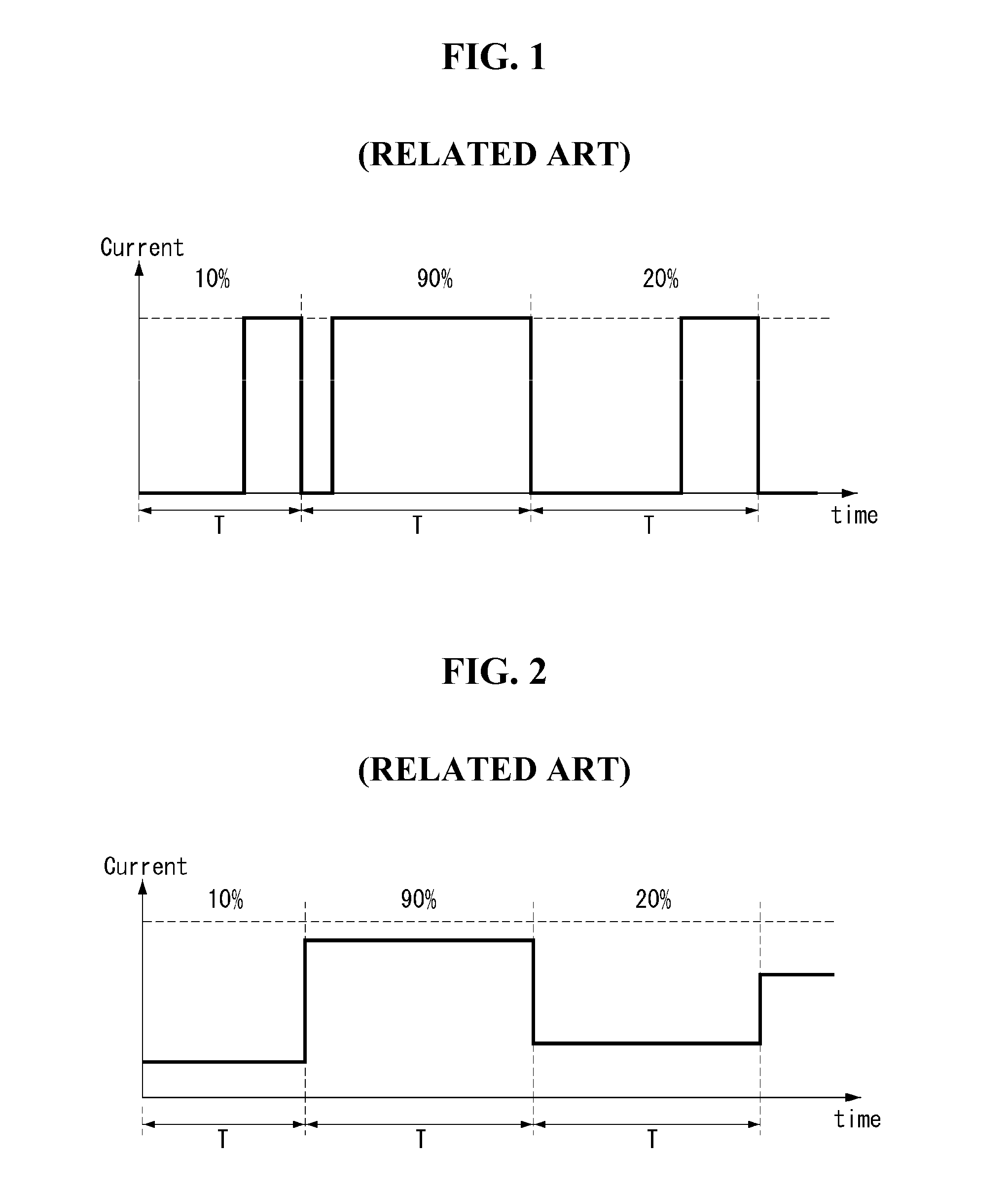
In the PAM control method, it is impossible to perform the backlight scanning drive and the local dimming drive.
Further, because the PAM control method controls the luminance of the LEDs using the amplitude of the pulse, it is difficult to achieve the low luminance.
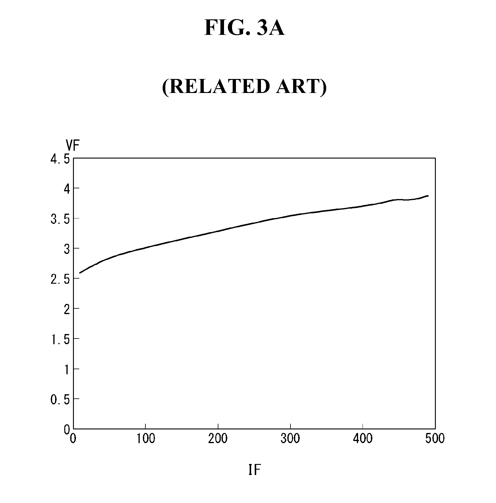
First, as shown in FIG. 3A, in the PWM control method, the forward voltage VF between both terminals of the LED increases in proportion to the forward current IF flowing in the LED. Because the forward current IF is fixed to a predetermined maximum value in the PWM control method, the forward voltage VF in the PWM control method is greater than that in the PAM control method. Thus, as shown in FIG. 3B, the power consumption, electromagnetic interference (EMI), and heat generation in the PWM control method are greater than those in the PAM control method.
Second, the amplitude of an input / output current in the PWM control method is greater than that in the PAM control method. Hence, more noise is generated by a repetition of compression and expansion resulting from a current flowing in a circuit part.
Third, because the PWM control method turns on and off the LEDs so as to control the luminance of the LEDs, a wavy noise is generated in a display image due to the turn-on and the turn-off of light energy.

Method used


Image

  • Backlight unit and liquid crystal display using the same
  • Backlight unit and liquid crystal display using the same
  • Backlight unit and liquid crystal display using the same

Examples


Embodiment Construction

[0037]Reference will now be made in detail to embodiments of the invention, examples of which are illustrated in the accompanying drawings. Wherever possible, the same reference numbers will be used throughout the drawings to refer to the same or like parts.

[0038]Exemplary embodiments of the invention will be described with reference to FIGS. 4 to 11.

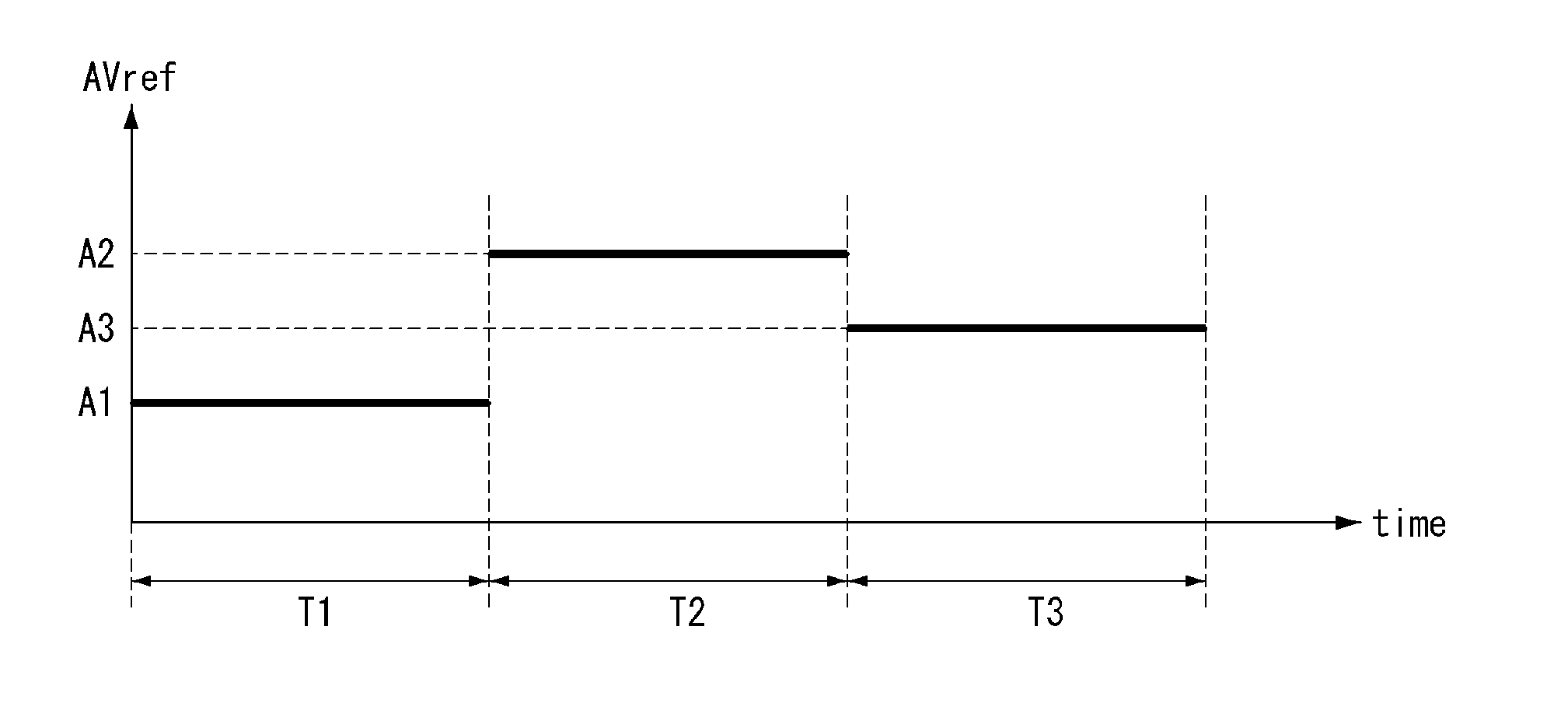
[0039]FIG. 4 schematically shows an example configuration of a backlight unit to which a light source driving device according to an exemplary embodiment of the invention is applied. FIG. 5 shows an example of a conditional pulse width and amplitude modulation (CPWAM) signal according to the embodiment of the invention.

[0040]As shown in FIG. 4, a backlight unit 40 according to the embodiment of the invention includes a light emitting diode (LED) array 30 having a plurality of LED channels CH1 to CHn and a light source driving device 20 for driving the LED channels CH1 to CHn. The light source driving device 20 includes a driving voltage...


PUM

PropertyMeasurementUnit
voltageaaaaaaaaaa
driving voltageaaaaaaaaaa
widthaaaaaaaaaa

Abstract

A liquid crystal display (LCD) device having an LCD panel with a plurality of pixels is disclosed. The LCD device includes gate and data driving circuits to provide a gate pulse and a data voltage to the pixels, respectively, and a timing controller to control the gate and data driving circuits. The LCD device also includes a backlight unit to provide light to the liquid crystal panel. The backlight unit includes a light source having at least one LED channel, a driving voltage generator to supply a driving voltage to the LED channel, and an LED driver to supply a conditional pulse width and amplitude modulation (CPWAM) signal to the LED channel. The CPWAM signal has a pulse with an amplitude and a width that are both variable from one period of a predetermined length to another period of the predetermined length.

Description

[0001]This application claims the benefit of Korea Patent Application No. 10-2013-0131789 filed in Korea on Oct. 31, 2013, which is incorporated herein by reference for all purposes as if fully set forth herein.BACKGROUND OF THE INVENTION[0002]1. Field of the Invention[0003]The present invention relates to a backlight unit and a liquid crystal display using the same, and more particularly, to a backlight unit and a liquid crystal display device using the same that can reduce one or more of power consumption, electromagnetic interference, heat generation, noise, and wavy noise.[0004]2. Discussion of the Related Art[0005]The use of flat panel displays has recently been growing exponentially. Among the flat panel displays, a liquid crystal display has been widely used in large-sized digital televisions requiring a thin profile, as well as in small-sized mobile devices requiring low power consumption.[0006]Because liquid crystal cells formed on a liquid crystal display panel of the liqu...

Claims


Application Information

Patent Timeline
Patent Type & Authority Applications(United States)
IPC IPC(8): G09G3/34G02F1/1335G09G3/36H05B33/08H05B44/00
CPCG09G3/342H05B33/083G02F1/133603G09G2320/0633G02F2001/133612G09G2320/0233G09G2330/021G09G3/36G09G3/3406G09G3/3648G09G2320/064H05B45/46H05B45/10G09G2360/145H05B45/37Y02B20/30G02F1/133612
Inventor LIM, SEONGHO
Owner LG DISPLAY CO LTD
Features
  • Generate Ideas
  • Intellectual Property
  • Life Sciences
  • Materials
  • Tech Scout
  • Unparalleled Data Quality
  • Higher Quality Content
  • 60% Fewer Hallucinations
Learn More