
Membrane reactor with divergent-flow channel

a membrane reactor and divergent flow technology, applied in the field of membrane reactors, can solve the problems of adverse configuration of the reaction pipeline and the sweep pipeline, and achieve the effects of improving the performance of the membrane reactor, reducing the flow velocity and increasing the reaction rate of the reactant gas

Inactive Publication Date: 2015-04-30
INST NUCLEAR ENERGY RES ROCAEC
View PDF1 Cites 5 Cited by
  • Summary
  • Abstract
  • Description
  • Claims
  • Application Information

AI Technical Summary

Benefits of technology

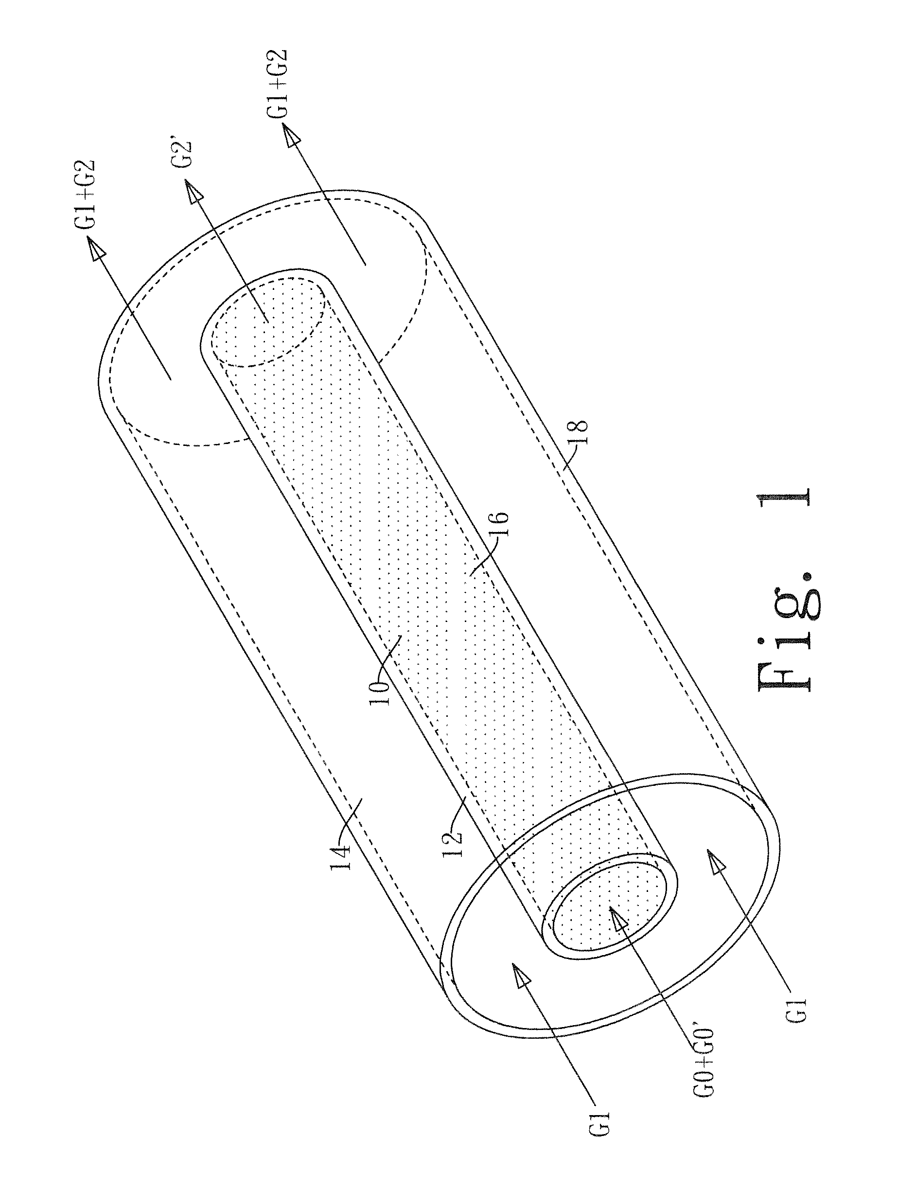
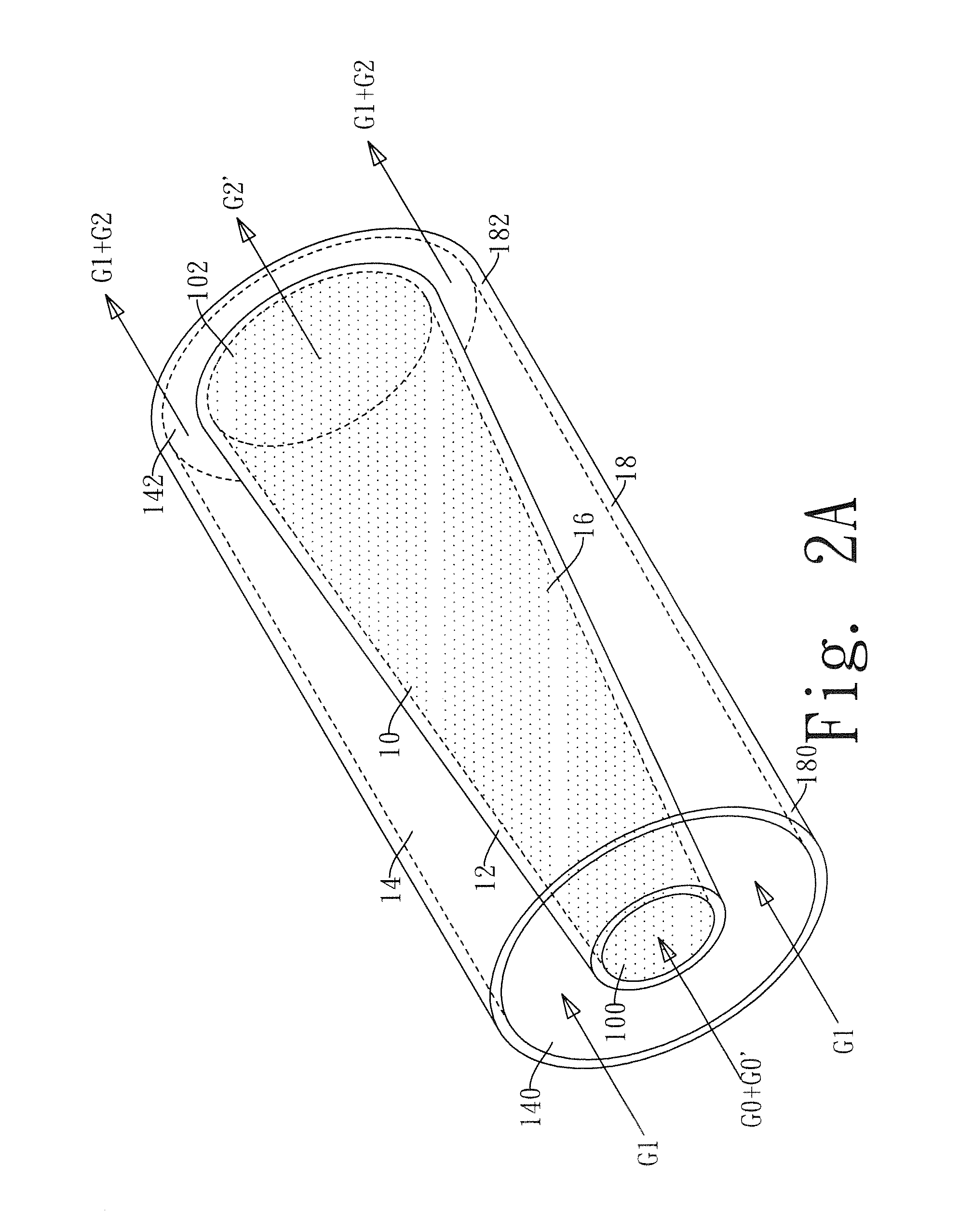
The present invention provides two types of membrane reactors with divergent-flow channel, which have a cross-sectional area increment from the upstream end to the downstream end and a sweep pipeline with a cross-sectional area decrease from the upstream to the downstream end. The flow velocity of the reactant gas is decreased from the upstream end to the downstream end, which extends the residence time of the reactant gas in the reaction pipeline and improves the performance of the membrane reactor due to longer reaction time. The cross-sectional area decrease of the sweep pipeline from the upstream end to the downstream end increases the flow velocity of the purge gas and enhances the removal rate of the product gas, which further improves the performance of the membrane reactor. These membrane reactors have improved reaction performance due to the decrease of the flow velocity of the reactant gas and the increase of the removal rate of the product gas.

Problems solved by technology

The difference between the membrane reactor with divergent flow channel and the previous one is that the configuration of the reaction pipeline and the sweep pipeline is adverse, in which the reaction pipeline is installed on an external side of the sweep pipeline, while the membrane is still installed between the reaction pipeline and the sweep pipeline to separate the reaction pipeline from the sweep pipeline.

Method used


Image

  • Membrane reactor with divergent-flow channel
  • Membrane reactor with divergent-flow channel
  • Membrane reactor with divergent-flow channel

Examples


Embodiment Construction

[0021]The technical characteristics of the present invention will become clearer in light of the following detailed description of illustrative preferred embodiments of this invention. It is intended that the preferred embodiments disclosed herein are to be considered illustrative rather than restrictive.

[0022]The diverging membrane reactor of the present invention is characterized by the structure of the reaction pipeline having a cross-sectional area increment from the upstream end to the downstream end to decrease the flow velocity of the reactant gas from the upstream end to the downstream end and extend the residence time of the reactant gas in the reaction pipeline. In the meantime, the structure of the sweep pipeline having a cross-sectional area decrement from the upstream end to the downstream end of the sweep pipeline to increase the flow velocity of the purge gas from the upstream end to the downstream end and enhance the removal of the product gas diffused to the sweep p...


PUM


Abstract

A membrane reactor with divergent-flow channel includes a reaction pipeline, a membrane and a purge (sweep) pipeline sequentially arranged from inside to outside or from outside to inside. The reaction pipeline has a cross-sectional area increment from the front (upstream) end to the rear (downstream) end, so that the flow velocity of a reactant gas is decreased from the upstream end to the downstream end to extend the residence time of the reactant gas and improve the reaction rate of the reactant gas. The sweep pipeline has a cross-sectional area decrement from the upstream end to the downstream end, so that the flow velocity of a purging (sweeping) gas is increased from the upstream end to the downstream end to accelerate the reactant gas, and a product gas generated from the reaction passes through the membrane and enters the sweep pipeline to improve the reaction efficiency.

Description

FIELD OF THE INVENTION[0001]The present invention relates to a membrane reactor, and more particularly to a membrane reactor with divergent-flow channel having a reaction pipeline with increasing cross-sectional area from the upstream end to the downstream end of the reaction pipeline, so that the flow velocity of a reactant gas passing through the reaction pipeline is decreased, so as to improve the reaction performance of the membrane reactor.BACKGROUND OF THE INVENTION[0002]In general, a membrane reactor used for chemical reactions primarily combines catalysis and membrane separation technology to promote the efficiency of the reactor, and thus the membrane reactor has both reaction catalysis and product separation functions. Compared with a conventional fixed-bed reactor, the membrane reactor can improve the yield rate and purity of the products significantly.[0003]The membrane reactor has the following characteristics:1. The membrane can be implemented to let the products be re...

Claims


Application Information

Patent Timeline
IPC IPC(8): B01J15/00
CPCB01J15/005B01J2219/00896B01J12/007B01J19/0093B01J19/2415B01J19/2425B01J19/244B01J19/2475B01J2219/00783B01J2219/00792B01J2219/00797B01J2219/00835B01J2219/0086B01J2219/00869B01J2219/00907B01J2219/1946C01B3/16C01B3/505C01B2203/0283C01B2203/041C01B2203/1041C01B2203/1047C01B2203/1076
Inventor CHYOU, YAU-PINLIN, YU-SHAOCHEN, PO-CHUANGSHEU, WEN-JENNCHEN, YEN-CHOCHEN, CHIEN-CHON
Owner INST NUCLEAR ENERGY RES ROCAEC
Learn More