
Fluid management system and methods

a technology of fluid management system and management system, applied in the field of fluid management system and method, to achieve the effect of preventing hemolysis of filtered red blood cells

Active Publication Date: 2015-04-30
BOSTON SCI SCIMED INC
View PDF8 Cites 71 Cited by
  • Summary
  • Abstract
  • Description
  • Claims
  • Application Information

AI Technical Summary

Benefits of technology

The present invention is a recirculating fluid management system for use in hysteroscopic and other endoscopic procedures. The system is designed to prevent the hemolysis (destruction) of filtered red blood cells, which can occur when blood cells are exposed to high pressure or certain chemicals. The system includes a filter with specific characteristics that work with the flow parameters of saline to prevent hemolysis. The filter has a capacity of at least 40 ml of blood, with a filtration capacity of at least 60 ml. The system maintains the pressure at the filter interface at a maximum of 100 psi and the back pressure caused by the height of the saline source is less than 3 psi. The controlled outflow rate through the filter is designed to prevent hemolysis of more than 5% of filtered red blood cells. The system can maintain the electrolyte concentration in the saline and prevent any effect on a coagulation pathway of a patient. The system can provide saline inflow and outflow at rates ranging from 0 ml / min to at least 500 ml / min. The filter characteristics and controlled outflow rate are designed to cause no change in electrolyte concentration and prevent hemolysis of filtered red blood cells.

Problems solved by technology

In a filtration system, hemolysis can be caused at the interface of the filter membrane by excessive pressure or flow rates in combination with inadequate filter capacity, oversized pores of the filter and / or uncontrolled back pressure on the filter which can affect the pressure gradient across the filter membrane.

Method used


Image

  • Fluid management system and methods
  • Fluid management system and methods
  • Fluid management system and methods

Examples


Embodiment Construction

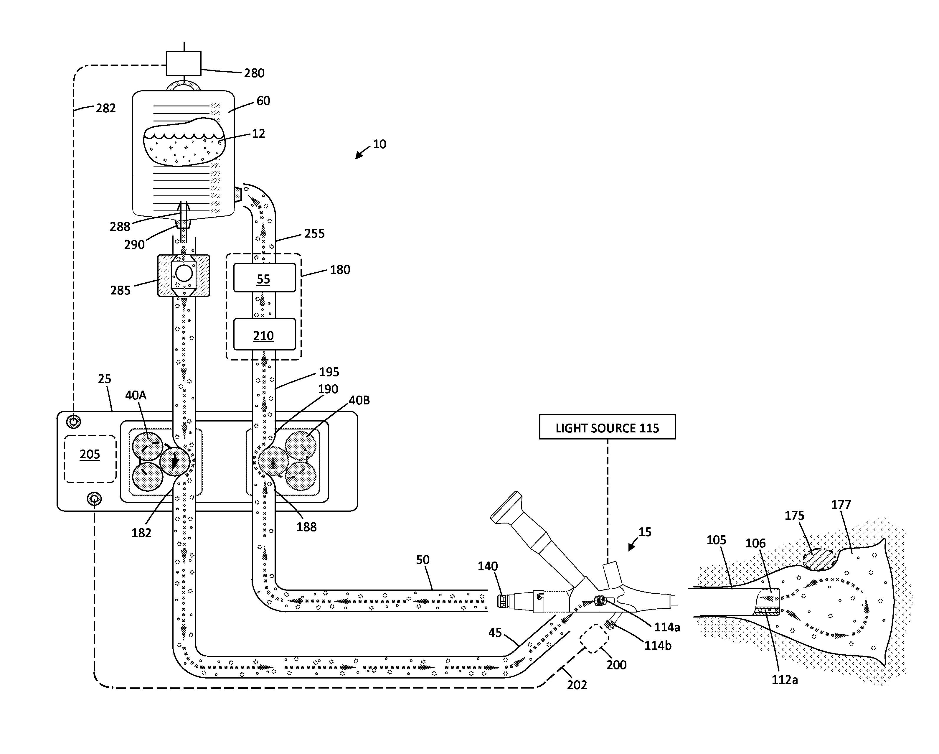
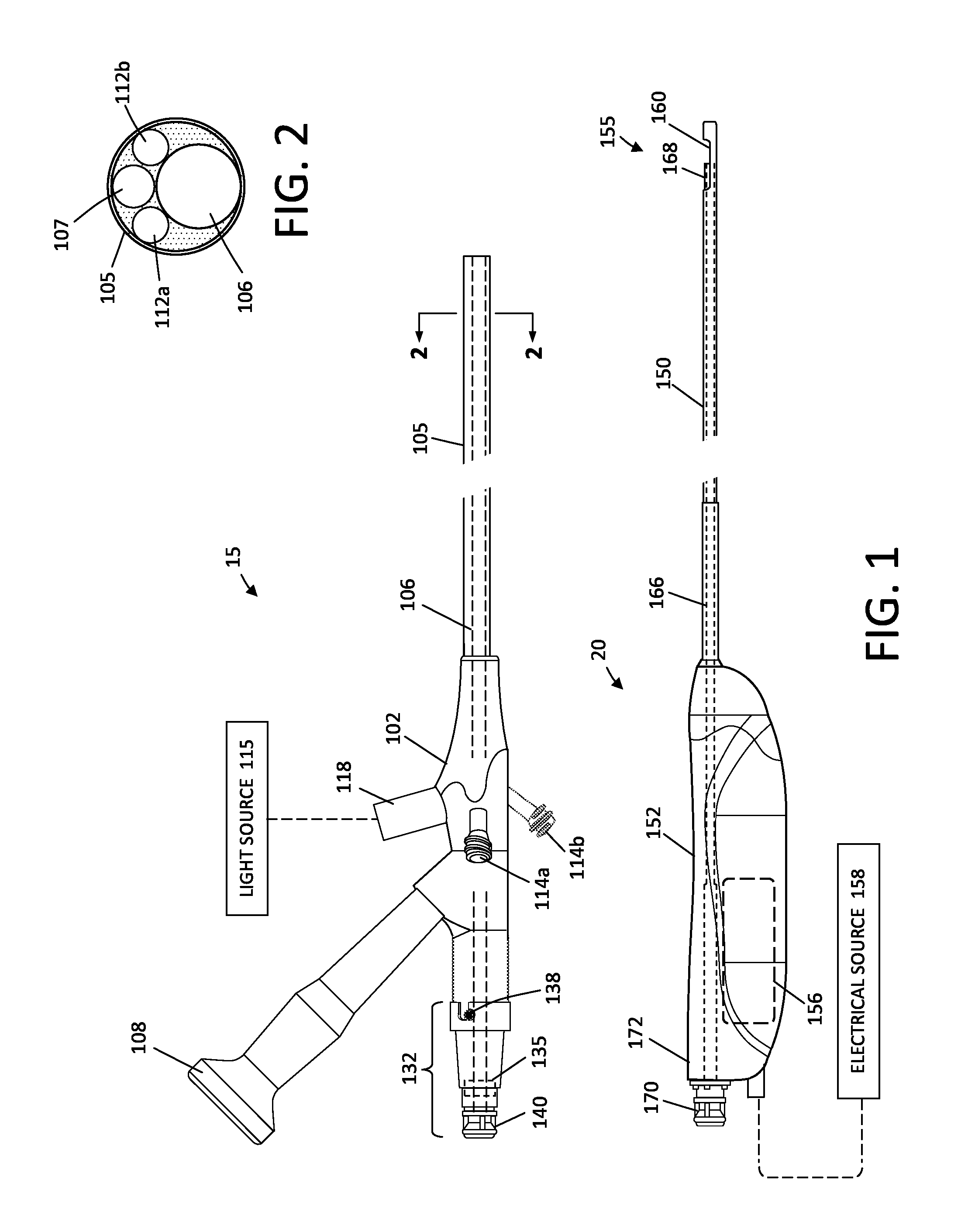
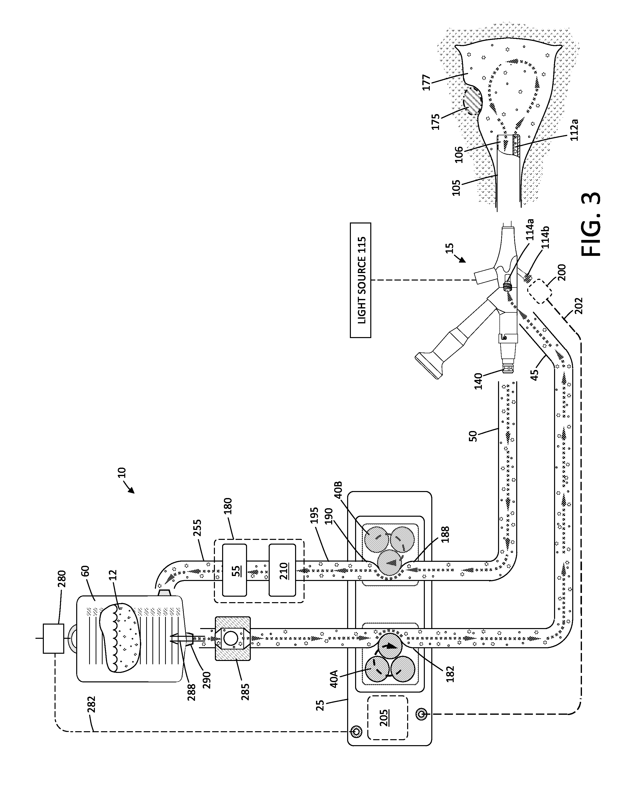
[0037]FIGS. 1-5 illustrate various components of a hysteroscopic system for performing a myomectomy or fibroid removal procedure. The myomectomy system integrates a re-circulating fluid management system 10 corresponding to the invention together with a known type of endoscope 15 and a motor driven resecting device 20.

[0038]More in particular, the fluid management system 10 is adapted to use saline solution 12 as a distention fluid to distend the uterine cavity and uses a controller 25 and first and second positive displacement pumps (40A and 40B) to re-circulate saline solution through an inflow line 45, outflow line 50 and molecular filter 55 back to a saline source 60. The controller 25 optionally can be adapted to control various operations of the motor driven resection device 20, such as on-off modulation, the speed of rotational and / or reciprocation of a cutting element, and activation of one or more electrodes or another energy emitter for resection or coagulation. Further, t...


PUM


Abstract

A hysteroscopic fluid management system includes a saline source with an electrolyte concentration, at least one pressure mechanism for circulating saline to and from a targeted site and through a filter having filter characteristics back to the source, and a controller. The controller provides a saline inflow in a first flow path to the site and a saline outflow in a second flow path from the site through the filter and back to the source at a controlled flow rate. A diagnostic or therapeutic procedure is performed at the site in the presence of the saline. The filter characteristics and the controlled flow rate are selected to (1) cause substantially no change in the electrolyte concentration in the saline, (2) to prevent hemolysis of greater than 5% of filtered red blood cells exposed to the saline, and / or (3) to minimize effect on prothrombin time of plasma exposed to the filter.

Description

CROSS-REFERENCE TO RELATED APPLICATIONS[0001]This application claims the benefit of provisional application No. 61 / 896,489 (Attorney Docket No. 41878-725.101), filed on Oct. 28, 2013, the full disclosure of which is incorporated herein by reference.FIELD OF THE INVENTION[0002]The present invention relates to fluid management systems and methods for use in diagnostic and operative hysteroscopic procedures, for example, for use in resecting and extracting uterine fibroid tissue, polyps and other abnormal uterine tissue.BACKGROUND OF THE INVENTION[0003]Uterine fibroids are non-cancerous tumors that develop in the wall of uterus. Such fibroids occur in a large percentage of the female population with some studies indicating up to 40 percent of all women have fibroids. Uterine fibroids can grow over time to be several centimeters in diameter and symptoms can include menorrhagia, reproductive dysfunction, pelvic pressure and pain.[0004]One current treatment of fibroids is hysteroscopic re...

Claims


Application Information

Patent Timeline
IPC IPC(8): A61M1/16
CPCA61M1/1603A61M1/1694A61B17/32002A61B17/42A61B2017/4216A61B2018/00559A61B2217/005A61B2217/007A61M2205/7545A61M2210/1433A61B18/1485A61B2018/00577A61B2018/00607A61B2018/00982A61B2218/002A61M2202/0429A61M2205/50A61M3/0208A61M3/0212A61M3/022A61M3/0229A61M1/777A61M1/77A61M1/34A61M2205/3331
Inventor GERMAIN, AARONKLEIN, KYLE
Owner BOSTON SCI SCIMED INC
Learn More