
Method for controlling a pressure control valve of a fuel injection system, in particular of a motor vehicle

a technology of pressure control valve and fuel injection system, which is applied in the direction of electrical control, process and machine control, etc., can solve the problems of negative effect on the material stability of the high-pressure system, pressure overshoot in the fuel accumulator, etc., and achieve the effect of reducing mechanical stress on the high-pressure components of the fuel metering system, reducing the mechanical stress of the high-pressure components, and ensuring the individual closing current control

Inactive Publication Date: 2015-04-30
ROBERT BOSCH GMBH
View PDF23 Cites 0 Cited by
  • Summary
  • Abstract
  • Description
  • Claims
  • Application Information

AI Technical Summary

Benefits of technology

This patent relates to a method for controlling the pressure in a fuel metering system of an automobile engine. The invention uses a learning function to accurately control the individual closing current of a pressure control valve, and prevents overpressure in the fuel accumulator by implementing an output pressure control function. This reduces mechanical stress on the high-pressure components of the fuel metering system and improves the overall performance of the system regardless of the operating mode. The method also prevents the need for a pressure stack-up, which would otherwise be necessary during the development of high-pressure components. Overall, the invention improves the behavior of the fuel metering system and contributes to the overall performance and reliability of the vehicle.

Problems solved by technology

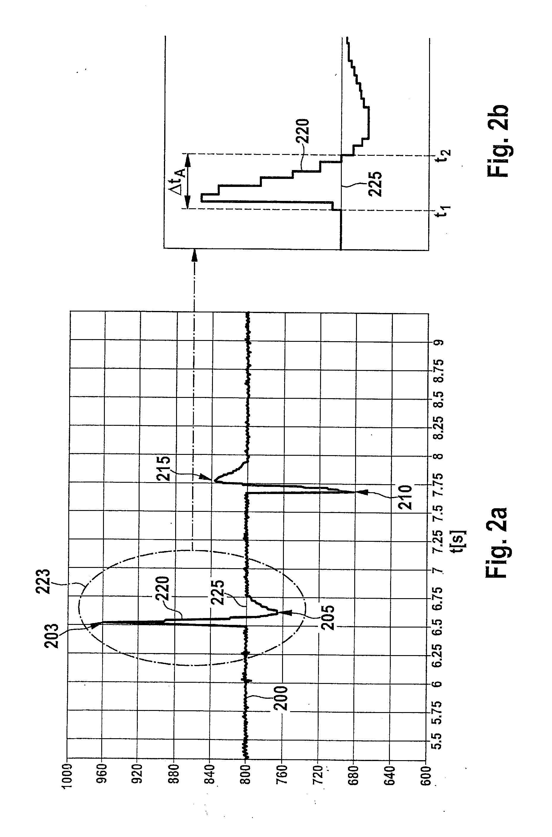
The close offset has the disadvantage that in operating situations of the internal combustion engine in which a rapid pressure reduction is necessary in the case of the closed pressure control valve, e.g., in the case of a transition from the full-load operation to the coasting mode, the above-mentioned reseating pressure input must initially be reduced before the pressure control valve may open for the purpose of effectuating the actual pressure reduction.
The delay of the pressure reduction resulting therefrom results in pressure overshoots in the fuel accumulator, since the pressure reduction takes place in a chronologically shifted manner with regard to the pressure changes which occur due to the fuel injection with the aid of injectors mentioned above.
This additionally results in individually differently high overshoots of the pressure in the fuel accumulator, which, in turn, has a negative effect on the material stability of the high-pressure system and must therefore be taken into consideration during a load collective test.

Method used


Image

  • Method for controlling a pressure control valve of a fuel injection
system, in particular of a motor vehicle
  • Method for controlling a pressure control valve of a fuel injection
system, in particular of a motor vehicle
  • Method for controlling a pressure control valve of a fuel injection
system, in particular of a motor vehicle

Examples


Embodiment Construction

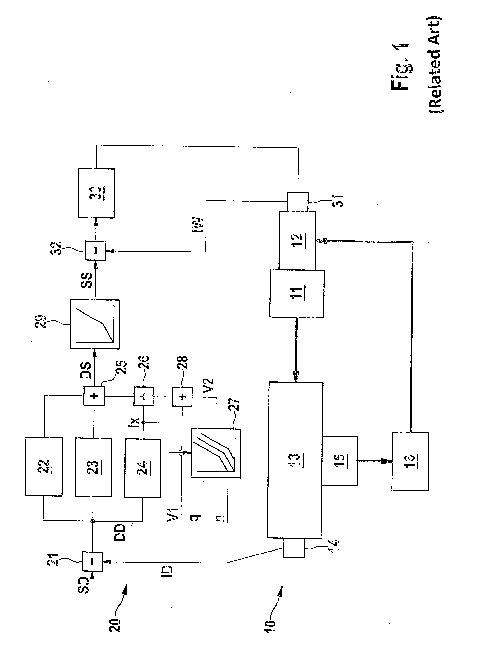
[0025]In FIG. 1, a fuel injection system 10 of an internal combustion engine is illustrated, a high-pressure fuel injection system of a diesel internal combustion engine for a motor vehicle may be involved. Fuel injection system 10 has a pump 11, in particular a high-pressure pump, which is supplied with fuel via a metering unit 12. Pump 11 is connected on the output side to a fuel accumulator 13, in which the fuel is stored under a pressure. In a manner which is not illustrated here, fuel accumulator 13 is connected to the injectors via which the fuel is injected into the combustion chambers of the internal combustion engine. A pressure control valve 15, with the aid of which the outflow of fuel from fuel accumulator 13 which is under high pressure (i.e., high-pressure accumulator) to a low-pressure accumulator 16 which is indicated only schematically takes place in a controlled manner, is connected to or situated at fuel accumulator 13, whereby the pressure is controllable in fuel...


PUM


Abstract

A method for controlling a pressure control valve which controls the pressure in a high-pressure accumulator of a fuel metering system of an internal combustion engine, fuel being metered into the combustion chambers of the internal combustion engine from the high-pressure accumulator, and the pressure control valve being connected to the high-pressure accumulator and controlling the outflow of fuel from the high-pressure accumulator into a low-pressure accumulator, and it being provided, in particular, that in the case of a closed pressure control valve, the energization of the pressure control valve is reduced until the pressure control valve opens, and a close offset input is ascertained based on the energization present at the opening of the pressure control valve.

Description

RELATED APPLICATION INFORMATION[0001]The present application claims priority to and the benefit of German patent application no. 10 2013 221 981.4, which was filed in Germany on Oct. 29, 2013, the disclosure of which is incorporated herein by reference.FIELD OF THE INVENTION[0002]The present invention relates to a method for controlling a pressure control valve of a fuel metering system of an internal combustion engine, in particular of a motor vehicle according to the definition of the species in Claim 1. Furthermore, the present invention relates to a computer program which carries out all steps of the method according to the present invention when it runs on an arithmetic unit or a control unit, as well as a computer program product having program code, which is stored on a machine-readable medium, for carrying out the method according to the present invention, when the program runs on an arithmetic unit or a control unit.BACKGROUND INFORMATION[0003]German patent document DE 10 2...

Claims


Application Information

Patent Timeline
Patent Type & Authority Applications(United States)
IPC IPC(8): F02D41/38
CPCF02D41/3845F02D41/123F02D41/20F02D41/3863F02D41/2464
Inventor JENNE, ACHIMHILLENBRAND, TOBIAS
Owner ROBERT BOSCH GMBH
Learn More