An electromechanical compound transmission device

A transmission device and composite technology, applied in the field of vehicle transmission, can solve the problems of high transmission power density and low transmission efficiency, and achieve the effects of high transmission power density, high efficiency power density and stable vehicle speed.

Active Publication Date: 2020-07-03
HEFEI UNIV OF TECH +1
View PDF5 Cites 0 Cited by
  • Summary
  • Abstract
  • Description
  • Claims
  • Application Information

AI Technical Summary

Problems solved by technology

The electric transmission system has the characteristics of high transmission power density, high flexibility in system structure layout, and easy realization of continuously variable transmission. However, compared with mechanical transmission, the transmission efficiency of electric transmission is relatively low.

Method used


Image

  • An electromechanical compound transmission device
  • An electromechanical compound transmission device

Examples


Embodiment

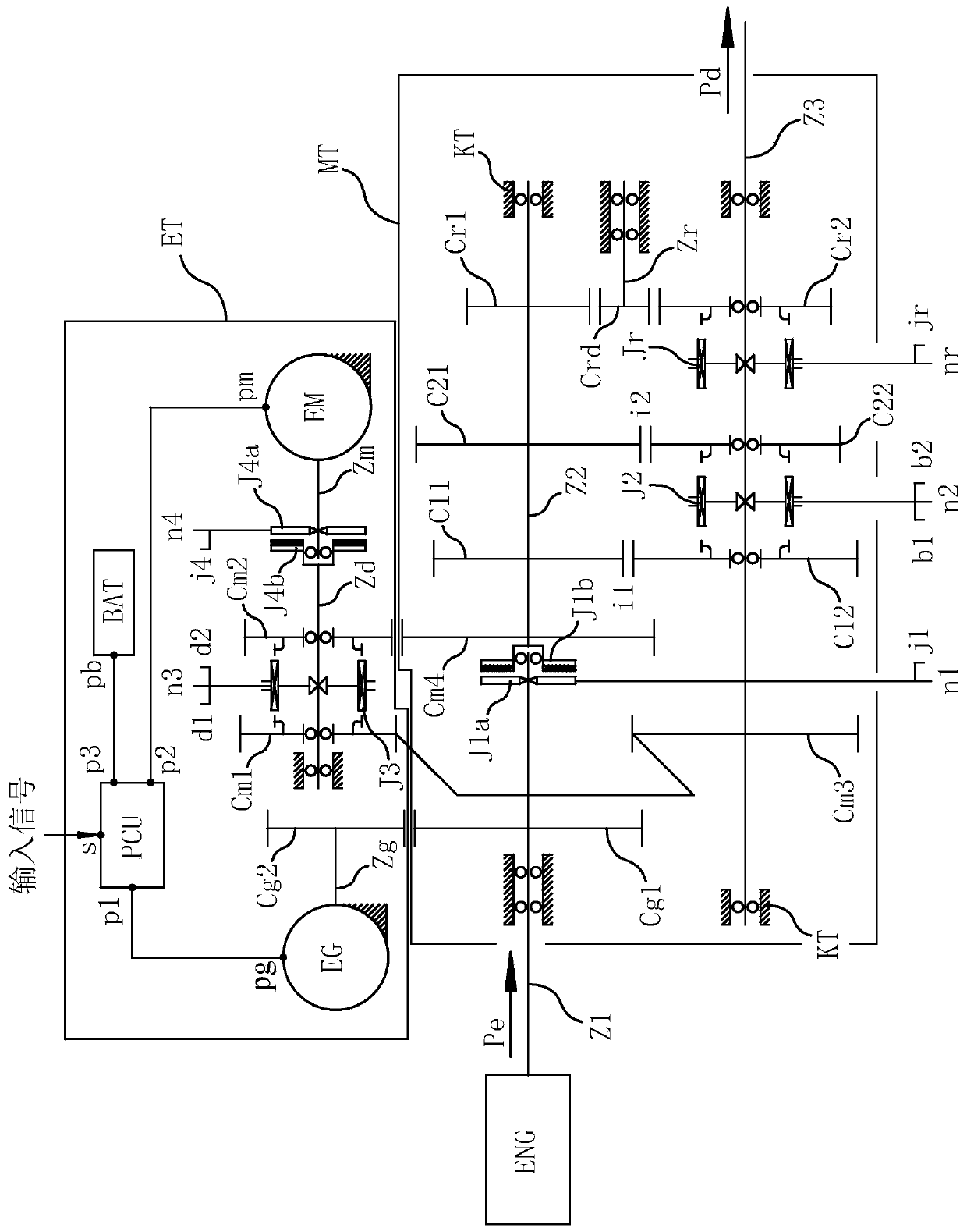
[0042] Embodiment: An electromechanical compound transmission device that can be applied to the vehicle transmission system (the mechanical forward gear is two gears)

[0043] See attached figure 1 , the electromechanical compound transmission device is composed of three parts: mechanical transmission module MT, electric transmission module ET and device housing KT.

[0044] The mechanical transmission module MT includes an input shaft Z1, an intermediate shaft Z2, an output shaft Z3 and an idler shaft Zr.

[0045] The input shaft Z1 is rotatably supported relative to the device housing KT, and a transfer drive gear Cg1 is fixed on the input shaft Z1, and one end of the input shaft Z1 is used as a power input end.

[0046] The intermediate shaft Z2 is rotatably supported relative to the device housing KT, the intermediate shaft Z2 is coaxially arranged with the input shaft Z1, and at the adjacent ends of the intermediate shaft Z2 and the input shaft Z1, a first clutch is shea...


PUM


Abstract

The invention relates to an electromechanical combined transmission device. The electromechanical combined transmission device is characterized by consisting of a mechanical transmission module and anelectric transmission module, wherein the mechanical transmission module comprises an input shaft, a middle shaft, an output shaft, a first clutch, at least two forward gear sets and forward adapters, wherein the forward gear sets carry out speed-variable transmission from a low speed to a high speed. The electric transmission module comprises a power generator, an electric motor, a second clutch, an electric motor shaft, an electric transmission shaft, a direct driving gear, a series-driving gear, an electric transmission connector, a current condenser and a power controller. According to the scheme, four different transmission modes can be formed by setting the working states of the clutches and the adapters and using the power controller for controlling the working states of the powergenerator, electric motor and current condenser, the advantages of reliable and efficient mechanical transmission, large power density of electric transmission, easy realization of stepless speed changing and the like are brought into play conveniently, the defects of mechanical transmission and electric transmission are avoided at the same time, and the electromechanical combined transmission device is suitable for loading different types of vehicles.

Description

technical field [0001] The invention belongs to the field of vehicle transmission, and in particular relates to an electromechanical composite transmission device which uses an internal combustion engine as a power source and comprehensively applies mechanical transmission and electric transmission. Background technique [0002] According to different functions and applicable occasions, vehicles can be roughly divided into two categories: road vehicles and non-road vehicles. Road vehicles are all kinds of vehicles used to transport passengers and goods on the artificial road network; non-road vehicles are all kinds of self-propelled construction machinery, agricultural equipment, construction machinery, special operation machinery and Non-road transport vehicles, military vehicles, etc. Whether it is a road vehicle or a non-road vehicle, it is necessary to control the driving speed to meet the work efficiency and quality requirements in different work scenarios during the w...

Claims


Application Information

Patent Timeline
Patent Type & Authority Patents(China)
IPC IPC(8): B60K17/08B60K17/12F16H57/023F16H63/34
Inventor 孙保群尹大乐严正峰施益平汪韶杰盛楠夏光
Owner HEFEI UNIV OF TECH
Why Eureka
Try Eureka